How to Use 7080g: Examples, Pinouts, and Specs
Introduction
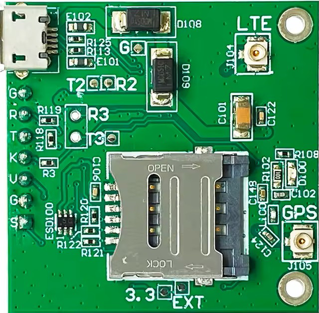
The SIM7080G is a multi-band LTE module designed for IoT applications. It supports various communication protocols, including GSM, GPRS, and NB-IoT, making it versatile for a wide range of use cases. With features such as GPS positioning, low power consumption, and a compact form factor, the SIM7080G is ideal for applications like remote monitoring, asset tracking, smart metering, and industrial automation.
Explore Projects Built with 7080g


Explore Projects Built with 7080g
Common Applications:
- Remote monitoring and control systems
- Asset tracking and fleet management
- Smart metering (e.g., water, gas, electricity)
- Environmental monitoring
- Industrial IoT (IIoT) applications
- Wearable devices with GPS functionality
Technical Specifications
Key Technical Details:
| Parameter | Specification |
|---|---|
| Communication Protocols | LTE Cat-M1, NB-IoT, GSM/GPRS |
| Frequency Bands | LTE: B1/B2/B3/B4/B5/B8/B12/B13/B18/B19/B20/B26/B28 |
| GPS Support | Yes (GNSS: GPS, GLONASS, BeiDou, Galileo, QZSS) |
| Operating Voltage | 3.0V to 4.3V (Typical: 3.8V) |
| Power Consumption | Idle: ~1.2mA, Active: ~20mA (LTE-M1) |
| Operating Temperature | -40°C to +85°C |
| Dimensions | 24mm x 24mm x 2.6mm |
| Interface | UART, I2C, GPIO, ADC, PWM |
Pin Configuration and Descriptions:
| Pin Number | Pin Name | Description |
|---|---|---|
| 1 | VCC | Power supply input (3.0V to 4.3V) |
| 2 | GND | Ground |
| 3 | TXD | UART Transmit |
| 4 | RXD | UART Receive |
| 5 | GPIO1 | General-purpose I/O pin |
| 6 | GPIO2 | General-purpose I/O pin |
| 7 | ADC | Analog-to-Digital Converter input |
| 8 | PWM | Pulse Width Modulation output |
| 9 | RESET | Reset pin (active low) |
| 10 | GNSS_TXD | GNSS UART Transmit |
| 11 | GNSS_RXD | GNSS UART Receive |
| 12 | NET_STATUS | Network status indicator |
Usage Instructions
How to Use the SIM7080G in a Circuit:
- Power Supply: Connect the VCC pin to a stable 3.8V power source and GND to ground. Ensure the power supply can handle peak current demands.
- UART Communication: Connect the TXD and RXD pins to a microcontroller or host device for serial communication. Use a logic level converter if the microcontroller operates at 5V logic.
- Antenna Connection: Attach an appropriate LTE and GNSS antenna to the module for reliable communication and GPS functionality.
- Network Configuration: Use AT commands to configure the module for the desired network (e.g., LTE-M1, NB-IoT).
- GNSS Functionality: Enable GNSS using AT commands to retrieve GPS data for location-based applications.
Important Considerations:
- Power Supply Stability: Ensure the power supply is stable and capable of handling peak currents (~2A during transmission bursts).
- Antenna Placement: Place the antennas away from noise sources to improve signal quality.
- Firmware Updates: Regularly update the module's firmware to ensure compatibility with network changes and to access new features.
- UART Baud Rate: Configure the UART baud rate to match the host device (default is typically 115200 bps).
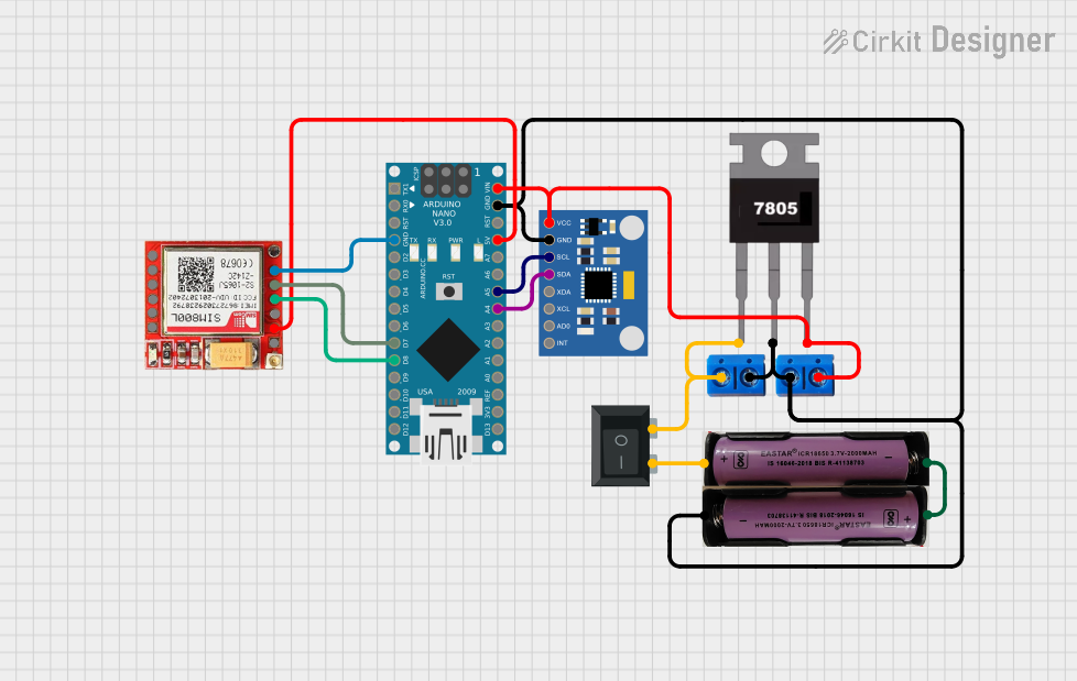
Example: Connecting SIM7080G to Arduino UNO
Below is an example of how to interface the SIM7080G with an Arduino UNO for basic communication:
Circuit Connections:
- SIM7080G
TXD→ ArduinoRX(Pin 0) - SIM7080G
RXD→ ArduinoTX(Pin 1) - SIM7080G
VCC→ External 3.8V power supply - SIM7080G
GND→ ArduinoGND
Arduino Code:
#include <SoftwareSerial.h>

// Define RX and TX pins for SoftwareSerial
SoftwareSerial sim7080(10, 11); // RX = Pin 10, TX = Pin 11

void setup() {
  Serial.begin(9600); // Initialize Serial Monitor
  sim7080.begin(9600); // Initialize SIM7080G communication

  Serial.println("Initializing SIM7080G...");
  delay(1000);

  // Send AT command to check communication
  sim7080.println("AT");
  delay(500);

  // Read response from SIM7080G
  while (sim7080.available()) {
    Serial.write(sim7080.read());
  }
}

void loop() {
  // Forward data from SIM7080G to Serial Monitor
  if (sim7080.available()) {
    Serial.write(sim7080.read());
  }

  // Forward data from Serial Monitor to SIM7080G
  if (Serial.available()) {
    sim7080.write(Serial.read());
  }
}
Notes:
- Use a logic level converter if the Arduino operates at 5V logic, as the SIM7080G uses 3.3V logic.
- Ensure the external power supply is stable and capable of providing sufficient current.
Troubleshooting and FAQs
Common Issues and Solutions:
No Response to AT Commands:
- Cause: Incorrect UART connection or baud rate mismatch.
- Solution: Verify TXD and RXD connections. Check and set the correct baud rate.
Module Not Connecting to Network:
- Cause: Poor signal strength or incorrect APN settings.
- Solution: Ensure the antenna is properly connected and placed. Configure the correct APN using the
AT+CGDCONTcommand.
High Power Consumption:
- Cause: Module is in active mode or transmitting frequently.
- Solution: Use power-saving modes (e.g., PSM or eDRX) to reduce power consumption.
GNSS Not Working:
- Cause: Antenna placement or insufficient satellite visibility.
- Solution: Place the GNSS antenna in an open area with a clear view of the sky.
FAQs:
Q: Can the SIM7080G operate on 5V logic?
A: No, the SIM7080G operates on 3.3V logic. Use a level shifter for 5V systems.Q: How do I update the firmware?
A: Firmware updates can be performed using the manufacturer's tools and a USB-to-UART adapter.Q: What is the typical GPS accuracy?
A: The SIM7080G provides GPS accuracy of approximately 2.5 meters under ideal conditions.Q: Can I use the SIM7080G for voice calls?
A: No, the SIM7080G is designed for data communication and does not support voice calls.
By following this documentation, users can effectively integrate the SIM7080G into their IoT projects and troubleshoot common issues.