How to Use 40 AMP DC BREAKER: Examples, Pinouts, and Specs
40 AMP DC Breaker Documentation
1. Introduction
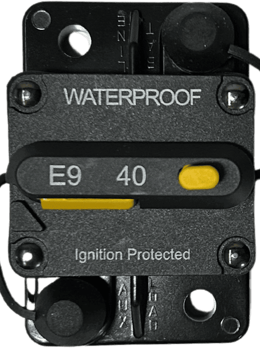
The 40 AMP DC Breaker is a protective device designed to interrupt the flow of direct current (DC) in a circuit when the current exceeds 40 amps. This ensures the safety of electrical components and prevents potential damage caused by overcurrent conditions. The breaker is an essential component in DC power systems, offering reliable protection and easy reset functionality.
Common Applications and Use Cases:
- Solar Power Systems: Protects solar charge controllers, inverters, and batteries from overcurrent.
- Automotive Applications: Used in vehicles to safeguard auxiliary systems like winches, audio amplifiers, and lighting.
- Marine Systems: Ensures safety in DC circuits on boats and yachts.
- Industrial Equipment: Protects DC motors, power supplies, and other heavy-duty equipment.
- Battery Banks: Prevents overcurrent in battery storage systems.
The 40 AMP DC Breaker is a robust and reusable alternative to traditional fuses, offering convenience and reliability in a wide range of applications.
2. Technical Specifications
The following table outlines the key technical details of the 40 AMP DC Breaker:
| Parameter | Specification |
|---|---|
| Rated Current | 40 Amps |
| Rated Voltage | 12V DC to 48V DC |
| Interrupting Capacity | 5,000 Amps @ 48V DC |
| Operating Temperature | -20°C to 60°C |
| Reset Type | Manual Reset |
| Mounting Style | Surface Mount or Panel Mount |
| Terminal Type | Screw Terminals |
| Dimensions | 75mm x 50mm x 25mm |
| Weight | ~150 grams |
| Compliance Standards | UL 1077, CE Certified |
Pin Configuration and Descriptions
| Pin/Terminal | Description |
|---|---|
| Terminal 1 (Input) | Connects to the positive side of the power source |
| Terminal 2 (Output) | Connects to the load (e.g., motor, inverter) |
| Reset Button | Used to manually reset the breaker after tripping |
3. Usage Instructions
How to Use the 40 AMP DC Breaker in a Circuit:
- Identify the Circuit: Determine the circuit where overcurrent protection is required.
- Connect the Input Terminal: Attach the positive wire from the power source (e.g., battery) to the Input Terminal of the breaker.
- Connect the Output Terminal: Attach the positive wire from the load (e.g., motor, inverter) to the Output Terminal of the breaker.
- Secure the Connections: Tighten the screw terminals to ensure a secure and reliable connection.
- Mount the Breaker: Use screws to mount the breaker on a panel or surface for stability.
- Power On the Circuit: Turn on the power source and verify that the breaker is functioning correctly.
Important Considerations and Best Practices:
- Ensure the breaker is rated for the voltage and current of your circuit.
- Use appropriately sized wires to handle the current without overheating.
- Avoid exposing the breaker to extreme temperatures or moisture.
- Regularly inspect the breaker for signs of wear or damage.
- Do not exceed the breaker's rated current (40 amps) to prevent tripping.
4. Example Application with Arduino UNO
The 40 AMP DC Breaker can be used in circuits involving an Arduino UNO to protect components like motors or high-power LEDs. Below is an example of how to integrate the breaker into a motor control circuit.
Circuit Diagram:
- Power Source: 12V DC battery
- Load: DC motor
- Control: Arduino UNO with an N-channel MOSFET
Arduino Code Example:
/*
  Example: Controlling a DC Motor with Arduino UNO and 40 AMP DC Breaker
  This code demonstrates how to control a DC motor using PWM while protecting
  the circuit with a 40 AMP DC breaker.
*/

const int motorPin = 9; // PWM pin connected to the MOSFET gate

void setup() {
  pinMode(motorPin, OUTPUT); // Set motorPin as an output
}

void loop() {
  // Gradually increase motor speed
  for (int speed = 0; speed <= 255; speed++) {
    analogWrite(motorPin, speed); // Set PWM duty cycle
    delay(20); // Wait for 20ms
  }

  // Gradually decrease motor speed
  for (int speed = 255; speed >= 0; speed--) {
    analogWrite(motorPin, speed); // Set PWM duty cycle
    delay(20); // Wait for 20ms
  }
}
Notes:
- The 40 AMP DC Breaker is placed between the battery's positive terminal and the motor's power input.
- Ensure the MOSFET is rated for the motor's current and voltage requirements.
- The breaker will trip if the motor draws more than 40 amps, protecting the Arduino and other components.
5. Troubleshooting and FAQs
Common Issues and Solutions:
| Issue | Possible Cause | Solution |
|---|---|---|
| Breaker trips frequently | Load exceeds 40 amps | Reduce the load or use a higher-rated breaker. |
| Breaker does not reset | Internal damage or persistent overcurrent | Inspect the breaker and circuit for faults. |
| No power to the load | Loose connections or tripped breaker | Check connections and reset the breaker. |
| Breaker feels hot during operation | High ambient temperature or poor ventilation | Improve ventilation or reduce load. |
FAQs:
Can I use the 40 AMP DC Breaker in an AC circuit?
No, this breaker is designed specifically for DC circuits. Using it in an AC circuit may result in malfunction or damage.What happens if the breaker trips?
The breaker will interrupt the circuit, cutting off power to the load. You can manually reset it by pressing the reset button.Can I use this breaker with a solar panel system?
Yes, the breaker is ideal for protecting solar charge controllers and batteries from overcurrent.How do I know if the breaker is tripped?
Most breakers have a visible indicator or a reset button that pops out when tripped.
This documentation provides a comprehensive guide to understanding, using, and troubleshooting the 40 AMP DC Breaker. Whether you're a beginner or an experienced user, this guide will help you integrate the breaker into your projects safely and effectively.
Explore Projects Built with 40 AMP DC BREAKER
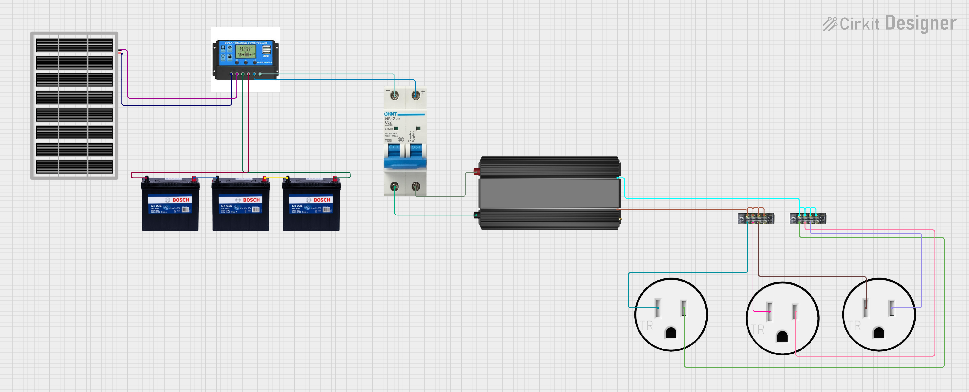
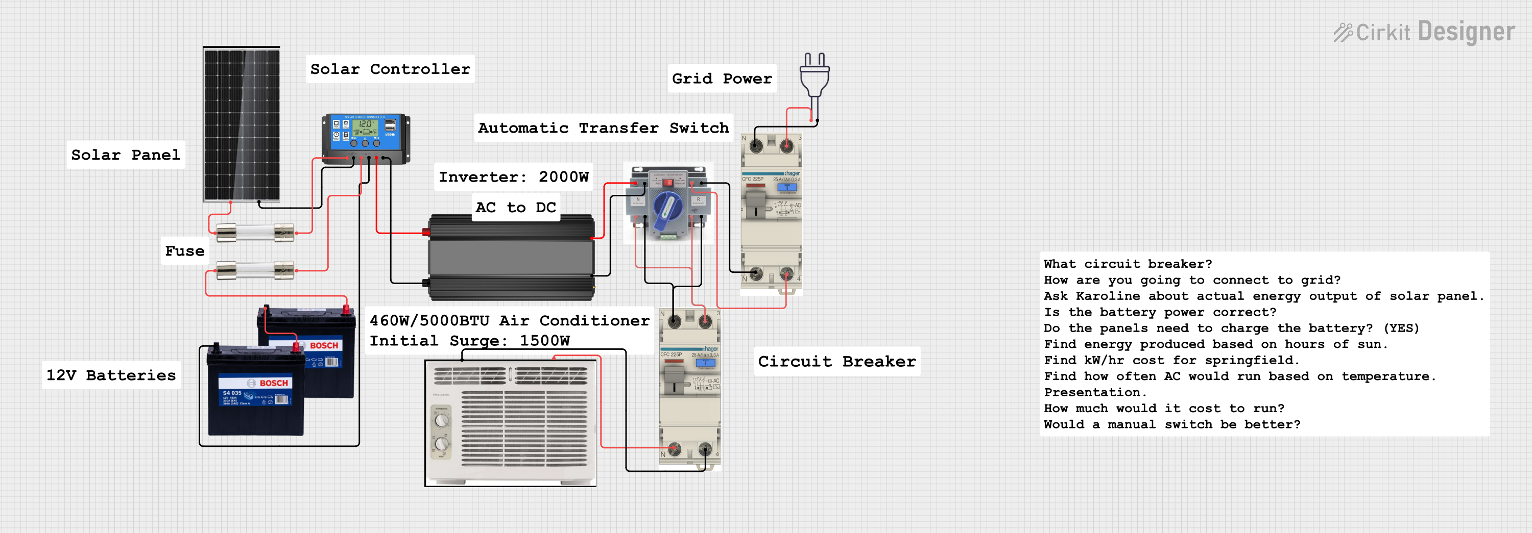

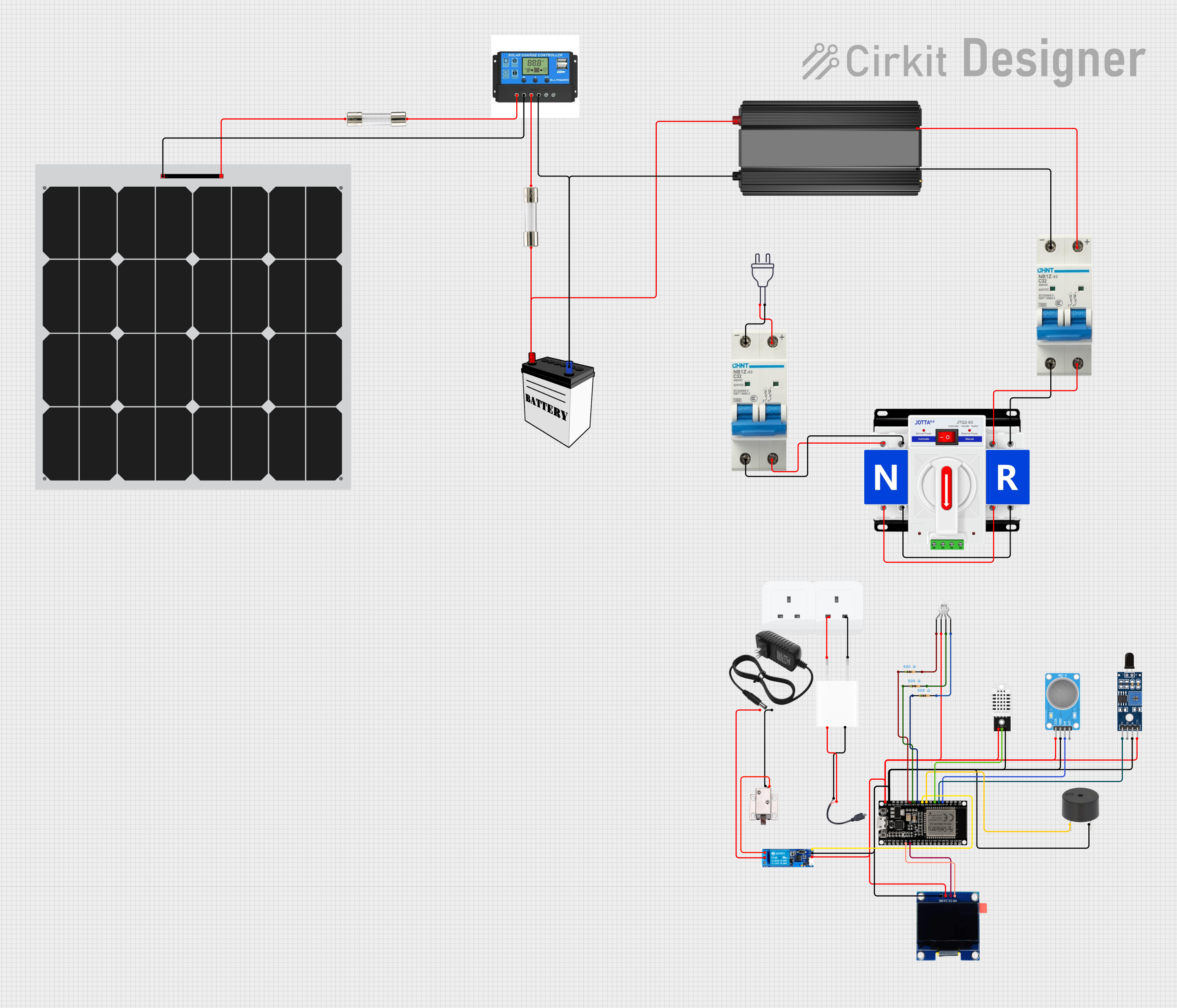
Explore Projects Built with 40 AMP DC BREAKER