How to Use 2 POLE ISOLATOR: Examples, Pinouts, and Specs

 Design with 2 POLE ISOLATOR in Cirkit Designer
2 Pole Isolator Documentation
Introduction
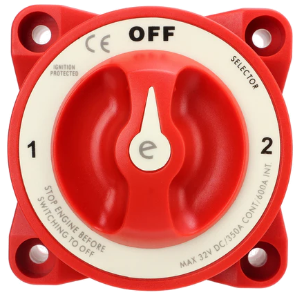
A 2 Pole Isolator is an electrical switch designed to disconnect two electrical circuits simultaneously. It is primarily used to isolate a circuit from its power supply, ensuring safety during maintenance or in the event of a fault. By breaking both the live and neutral connections, the 2 pole isolator provides a complete disconnection, making it an essential component in electrical systems where safety and reliability are critical.
Common Applications and Use Cases
- Residential and Commercial Electrical Systems: Used in distribution boards to isolate circuits for maintenance or emergencies.
- Industrial Equipment: Ensures safe disconnection of machinery during servicing or repairs.
- Solar Power Systems: Disconnects solar panels from inverters for maintenance or safety purposes.
- HVAC Systems: Isolates air conditioning or heating units for servicing.
- Motor Control Circuits: Provides a safe way to disconnect motors from the power supply.
Technical Specifications
The following table outlines the key technical specifications of a typical 2 Pole Isolator:
| Parameter | Specification |
|---|---|
| Number of Poles | 2 (Live and Neutral) |
| Rated Voltage | 240V AC (typical for residential use) |
| Rated Current | 20A, 32A, 63A (varies by model) |
| Frequency | 50/60 Hz |
| Insulation Voltage | 500V AC |
| Breaking Capacity | 6kA (typical for standard isolators) |
| Mounting Type | DIN Rail or Panel Mount |
| Operating Temperature | -20°C to +55°C |
| IP Rating | IP20 (indoor use) or higher for outdoor use |
Pin Configuration and Descriptions
The 2 Pole Isolator typically has four terminals, as described below:
| Terminal | Description |
|---|---|
| L1 (Input) | Live input terminal for the first circuit |
| N1 (Input) | Neutral input terminal for the first circuit |
| L2 (Output) | Live output terminal for the first circuit |
| N2 (Output) | Neutral output terminal for the first circuit |
Usage Instructions
How to Use the 2 Pole Isolator in a Circuit
- Identify the Circuit: Determine the circuit you want to isolate (e.g., a lighting circuit, motor, or appliance).
- Turn Off Power: Before installation, ensure the main power supply is turned off to avoid electrical hazards.
- Connect the Input Terminals:
- Connect the live wire to the L1 (Input) terminal.
- Connect the neutral wire to the N1 (Input) terminal.
- Connect the Output Terminals:
- Connect the live wire of the load to the L2 (Output) terminal.
- Connect the neutral wire of the load to the N2 (Output) terminal.
- Secure the Isolator: Mount the isolator on a DIN rail or panel as per the installation requirements.
- Test the Connection: After installation, turn on the power supply and test the isolator by switching it on and off to ensure proper operation.
Important Considerations and Best Practices
- Load Rating: Ensure the isolator's current and voltage ratings match the circuit's requirements.
- Proper Wiring: Double-check all connections to avoid loose or incorrect wiring.
- Environmental Conditions: Use an isolator with an appropriate IP rating for outdoor or harsh environments.
- Regular Maintenance: Periodically inspect the isolator for signs of wear, corrosion, or damage.
- Compliance: Ensure the isolator complies with local electrical standards and regulations.
Troubleshooting and FAQs
Common Issues and Solutions
| Issue | Possible Cause | Solution |
|---|---|---|
| Isolator does not switch on/off | Loose or incorrect wiring | Check and tighten all connections. |
| Circuit remains live after switching off | Faulty isolator or incorrect installation | Replace the isolator or recheck wiring. |
| Overheating of the isolator | Overloaded circuit | Ensure the load does not exceed the isolator's rating. |
| Sparks or arcing during operation | Worn-out contacts or high inrush current | Replace the isolator or use a higher-rated model. |
Frequently Asked Questions
Can a 2 Pole Isolator be used for DC circuits?
- Yes, but ensure the isolator is specifically rated for DC applications, as DC arcs are harder to extinguish than AC arcs.
What is the difference between a 2 Pole Isolator and a Circuit Breaker?
- A 2 Pole Isolator is a manual switch used for isolation, while a circuit breaker provides automatic protection against overcurrent and short circuits.
Can I use a 2 Pole Isolator for single-phase circuits?
- Yes, a 2 Pole Isolator is ideal for single-phase circuits as it disconnects both the live and neutral wires.
How do I choose the right isolator for my application?
- Consider the circuit's voltage, current, and environmental conditions. Select an isolator with appropriate ratings and certifications.
Example Circuit with Arduino UNO
While a 2 Pole Isolator is not directly connected to an Arduino UNO, it can be used in circuits where the Arduino controls a load (e.g., a motor or light) via a relay. Below is an example of how an isolator can be integrated into such a system:
Circuit Description
- The Arduino controls a relay module.
- The relay switches the load, which is connected through the 2 Pole Isolator.
- The isolator provides a manual disconnection option for safety.
Arduino Code Example
// Example code to control a relay module with Arduino
// The relay switches a load connected through a 2 Pole Isolator

const int relayPin = 7; // Pin connected to the relay module

void setup() {
  pinMode(relayPin, OUTPUT); // Set relay pin as output
  digitalWrite(relayPin, LOW); // Ensure relay is off at startup
}

void loop() {
  // Turn the relay on (load connected)
  digitalWrite(relayPin, HIGH);
  delay(5000); // Keep the relay on for 5 seconds

  // Turn the relay off (load disconnected)
  digitalWrite(relayPin, LOW);
  delay(5000); // Keep the relay off for 5 seconds
}
Important Notes
- Ensure the relay module is rated for the load being switched.
- The 2 Pole Isolator should be installed between the relay and the load for manual disconnection.
Conclusion
The 2 Pole Isolator is a vital component for ensuring electrical safety and enabling maintenance in various applications. By understanding its specifications, proper usage, and troubleshooting techniques, users can maximize its effectiveness and reliability. Always follow best practices and consult a qualified electrician for installation in complex systems.
Explore Projects Built with 2 POLE ISOLATOR

 Open Project in Cirkit Designer
 Open Project in Cirkit Designer
 Open Project in Cirkit Designer
 Open Project in Cirkit Designer
Explore Projects Built with 2 POLE ISOLATOR

 Open Project in Cirkit Designer
 Open Project in Cirkit Designer
 Open Project in Cirkit Designer
 Open Project in Cirkit Designer