
How to Use Rhino Industrial Brushless DC (BLDC) Motor Driver 50W with UART ASCII Compatible 10 to 30V 5A: Examples, Pinouts, and Specs
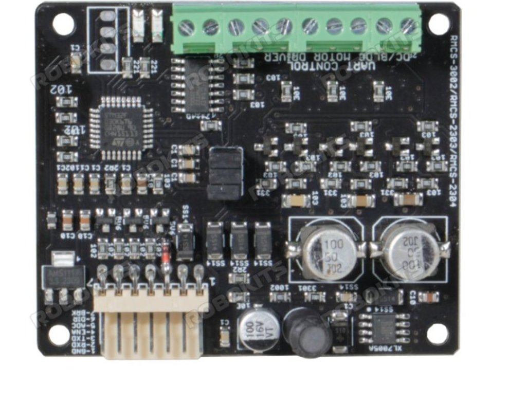
 Design with Rhino Industrial Brushless DC (BLDC) Motor Driver 50W with UART ASCII Compatible 10 to 30V 5A in Cirkit Designer
Introduction
The Rhino Industrial Brushless DC (BLDC) Motor Driver (RMCS-3002) is a high-performance motor driver designed to control brushless DC motors with precision and efficiency. Manufactured by RHINO MOTION CONTROLS, this driver is capable of delivering up to 50W of power, making it suitable for a wide range of industrial and robotics applications. It operates within a voltage range of 10 to 30V and supports a maximum current of 5A. The driver features UART ASCII compatibility, enabling seamless communication with microcontrollers and other control systems.
Explore Projects Built with Rhino Industrial Brushless DC (BLDC) Motor Driver 50W with UART ASCII Compatible 10 to 30V 5A
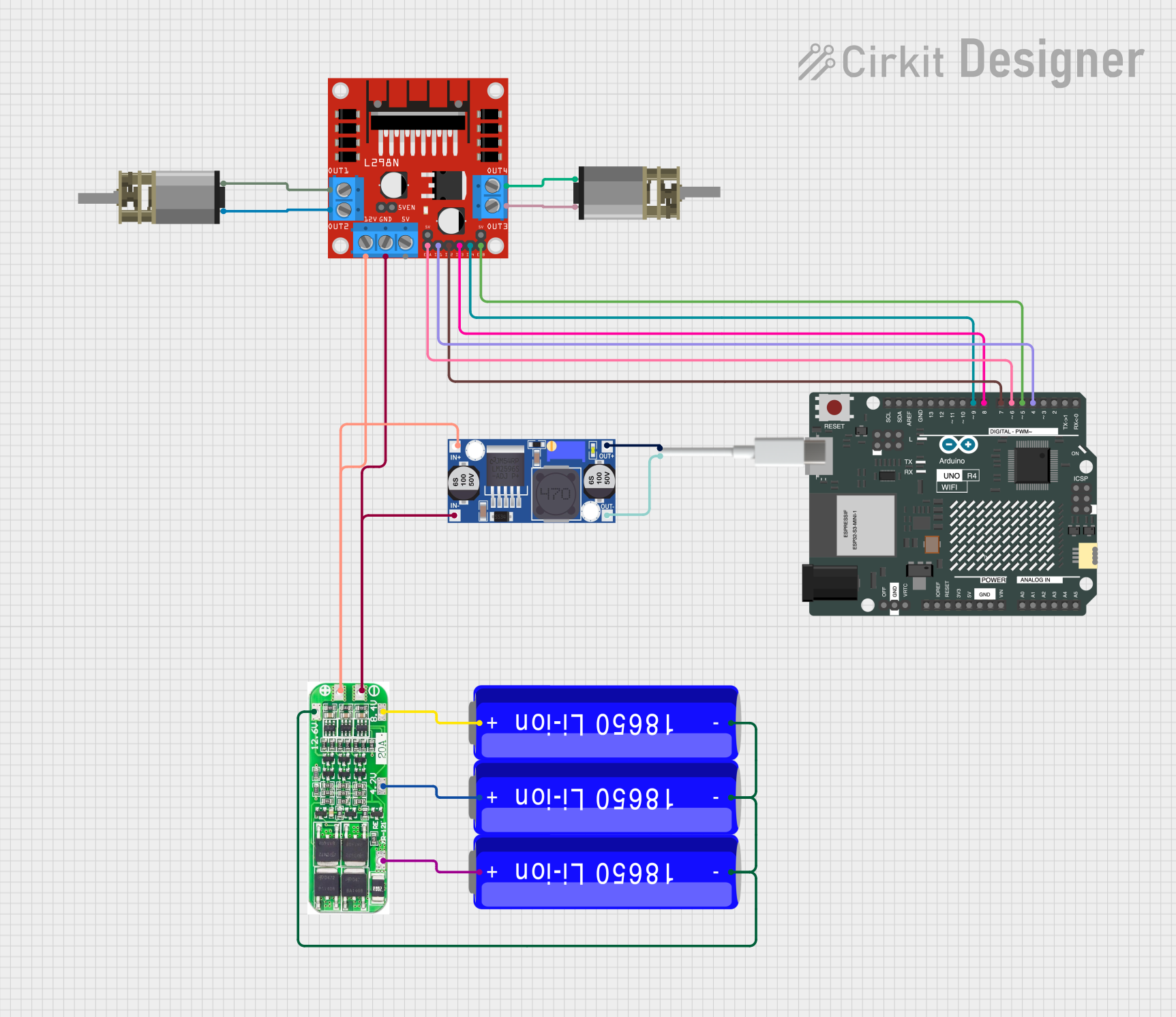 Open Project in Cirkit Designer
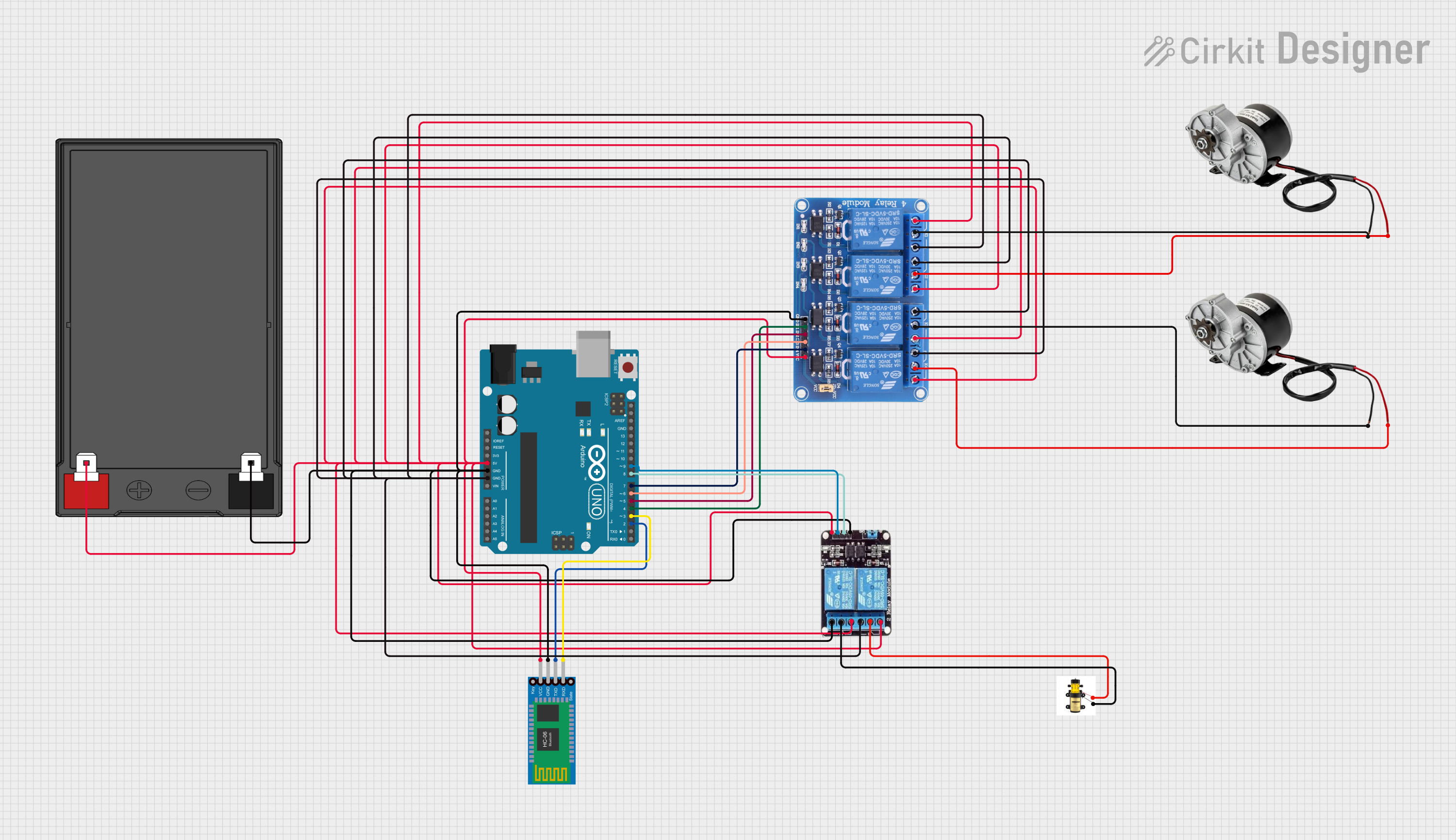 Open Project in Cirkit Designer
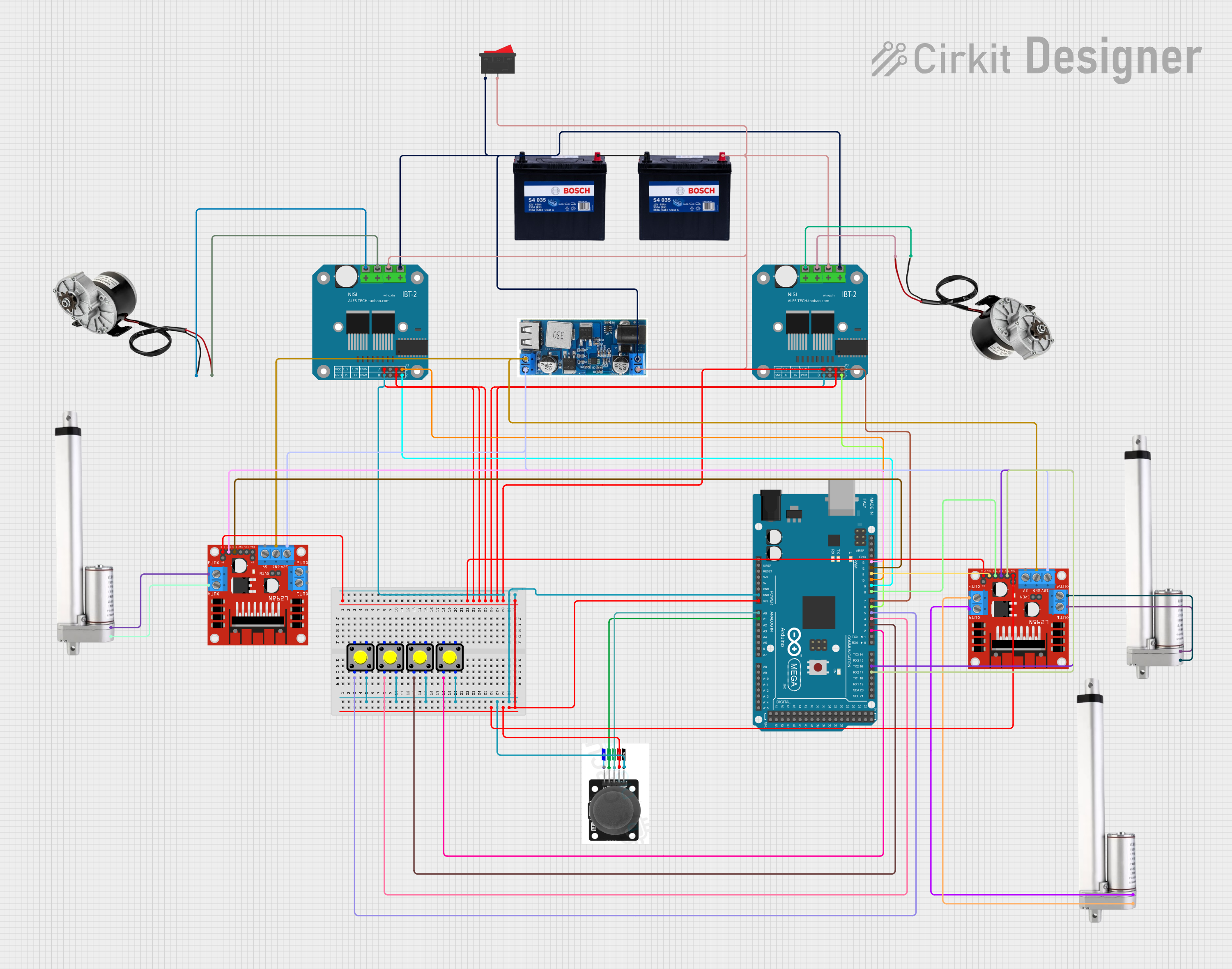 Open Project in Cirkit Designer
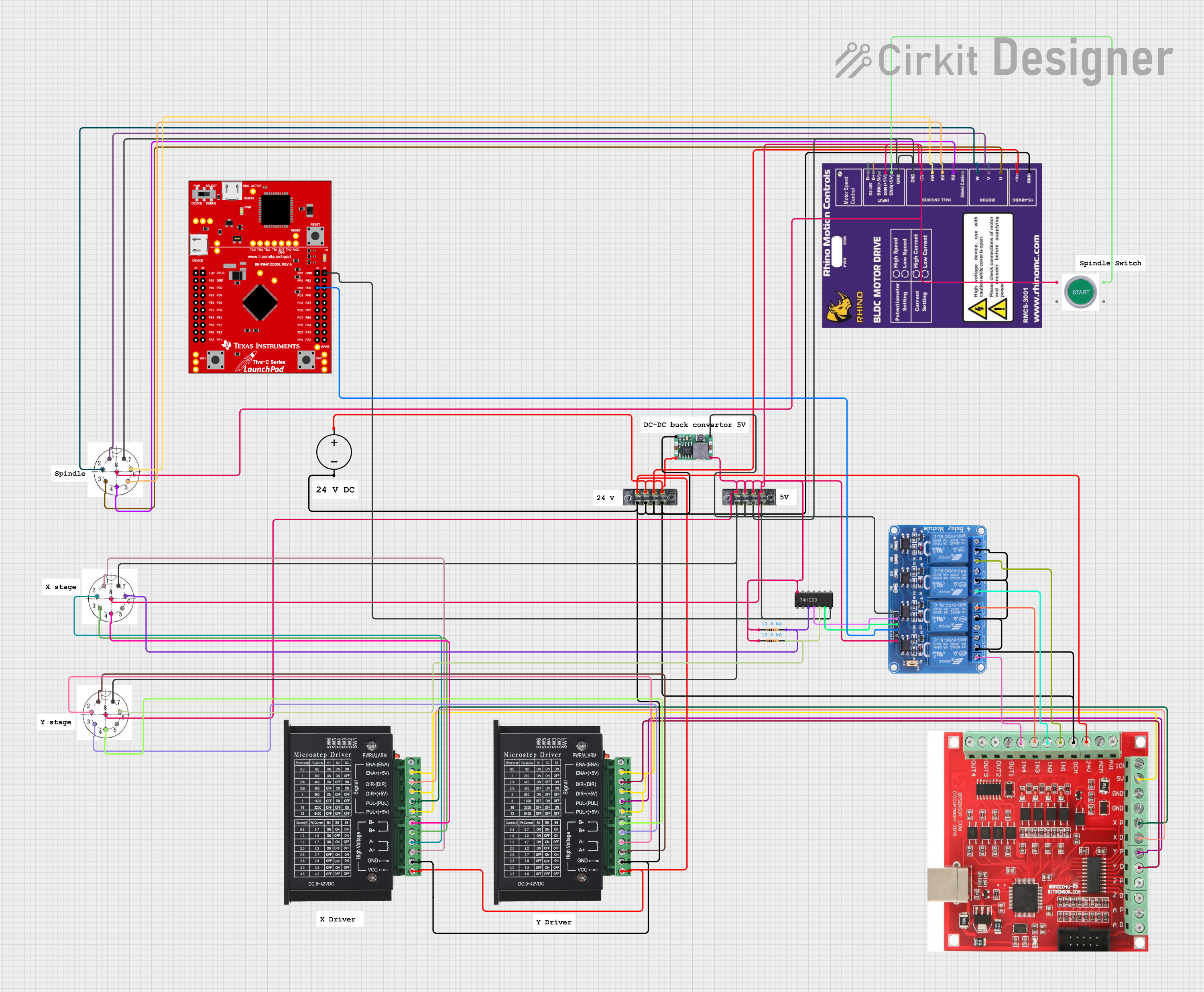 Open Project in Cirkit Designer
Explore Projects Built with Rhino Industrial Brushless DC (BLDC) Motor Driver 50W with UART ASCII Compatible 10 to 30V 5A
Open Project in Cirkit DesignerOpen Project in Cirkit DesignerOpen Project in Cirkit DesignerOpen Project in Cirkit DesignerCommon Applications
- Industrial automation systems
- Robotics and motion control
- Conveyor belt systems
- CNC machines
- Electric vehicles and drones
- Laboratory equipment requiring precise motor control
Technical Specifications
Key Technical Details
| Parameter | Specification |
|---|---|
| Manufacturer | RHINO MOTION CONTROLS |
| Part ID | RMCS-3002 |
| Motor Type Supported | Brushless DC (BLDC) |
| Power Output | Up to 50W |
| Input Voltage Range | 10V to 30V |
| Maximum Current | 5A |
| Communication Protocol | UART ASCII |
| Control Modes | Speed, Direction, and Torque |
| Operating Temperature | -10°C to 50°C |
| Dimensions | 75mm x 50mm x 25mm |
| Weight | 100g |
Pin Configuration and Descriptions
| Pin Number | Pin Name | Description |
|---|---|---|
| 1 | VIN+ | Positive input voltage (10V to 30V) |
| 2 | VIN- | Negative input voltage (Ground) |
| 3 | MOTOR_A | Motor phase A connection |
| 4 | MOTOR_B | Motor phase B connection |
| 5 | MOTOR_C | Motor phase C connection |
| 6 | UART_TX | UART Transmit pin for communication |
| 7 | UART_RX | UART Receive pin for communication |
| 8 | ENABLE | Enable pin to activate the motor driver (Active HIGH) |
| 9 | GND | Ground connection for logic and communication |
| 10 | SPEED_CTRL | Analog input for speed control (0-5V corresponds to 0-100% speed) |
Usage Instructions
How to Use the Component in a Circuit
- Power Supply: Connect a DC power supply (10V to 30V) to the
VIN+andVIN-pins. Ensure the power supply can deliver sufficient current (at least 5A). - Motor Connection: Connect the three phases of the BLDC motor to the
MOTOR_A,MOTOR_B, andMOTOR_Cpins. Ensure the connections match the motor's wiring diagram. - UART Communication: Connect the
UART_TXandUART_RXpins to the corresponding pins on a microcontroller (e.g., Arduino UNO). Use a common ground (GND) between the driver and the microcontroller. - Enable Pin: Set the
ENABLEpin HIGH to activate the motor driver. This can be controlled via a microcontroller or manually using a switch. - Speed Control: Provide an analog voltage (0-5V) to the
SPEED_CTRLpin to control the motor speed. A higher voltage corresponds to a higher speed.
Important Considerations and Best Practices
- Heat Dissipation: Ensure proper ventilation or use a heatsink if the driver operates near its maximum power rating.
- Wiring: Use appropriately rated wires for power and motor connections to avoid overheating or voltage drops.
- UART Communication: Use a baud rate of 9600 bps (default) for UART communication. Refer to the manufacturer's documentation for changing the baud rate if needed.
- Reverse Polarity Protection: The driver does not have built-in reverse polarity protection. Double-check power connections before powering on.
- Startup Sequence: Always enable the driver (
ENABLEpin HIGH) after connecting the motor and power supply.
Example Code for Arduino UNO
Below is an example code snippet to control the RMCS-3002 using an Arduino UNO via UART:
// Example code to control RMCS-3002 via UART
// Ensure the TX and RX pins of the Arduino are connected to the RX and TX pins
// of the motor driver, respectively. Use a common ground (GND).

#include <SoftwareSerial.h>

// Define UART pins for communication with RMCS-3002
SoftwareSerial motorDriver(10, 11); // RX, TX

void setup() {
  // Initialize serial communication
  Serial.begin(9600);              // For debugging via Serial Monitor
  motorDriver.begin(9600);         // UART communication with motor driver

  // Enable the motor driver
  pinMode(8, OUTPUT);              // Pin 8 connected to ENABLE pin
  digitalWrite(8, HIGH);           // Set ENABLE pin HIGH to activate driver

  Serial.println("Motor driver initialized.");
}

void loop() {
  // Send speed control command via UART
  // Example: "SPEED:50" sets motor speed to 50% (adjust as needed)
  motorDriver.println("SPEED:50");

  // Add a delay for demonstration purposes
  delay(1000);

  // Stop the motor
  motorDriver.println("SPEED:0");
  delay(1000);
}
Troubleshooting and FAQs
Common Issues and Solutions
Motor Does Not Spin
Cause: The
ENABLEpin is not set HIGH.Solution: Ensure the
ENABLEpin is connected to a HIGH signal (5V).Cause: Incorrect motor wiring.
Solution: Verify the connections to
MOTOR_A,MOTOR_B, andMOTOR_C.
Overheating
- Cause: Operating near maximum power without proper cooling.
- Solution: Use a heatsink or ensure adequate ventilation.
No UART Communication
- Cause: Incorrect baud rate or wiring.
- Solution: Ensure the baud rate is set to 9600 bps and check the TX/RX connections.
Speed Control Not Working
- Cause: Incorrect voltage on the
SPEED_CTRLpin. - Solution: Provide a 0-5V analog signal to the
SPEED_CTRLpin.
- Cause: Incorrect voltage on the
FAQs
Can I use this driver with a 24V power supply?
- Yes, the driver supports input voltages between 10V and 30V.
What happens if I exceed the 5A current limit?
- The driver may shut down or become damaged. Use a motor that operates within the specified current range.
Is the driver compatible with PWM signals for speed control?
- No, the
SPEED_CTRLpin requires an analog voltage input (0-5V).
- No, the
Can I change the UART baud rate?
- Yes, refer to the manufacturer's documentation for instructions on changing the baud rate.
This concludes the documentation for the Rhino Industrial Brushless DC (BLDC) Motor Driver (RMCS-3002). For further assistance, consult the manufacturer's support resources.