How to Use MCP9808: Examples, Pinouts, and Specs
Introduction
The MCP9808 is a high-accuracy digital temperature sensor with an I2C interface, capable of measuring temperatures from -40°C to +125°C with a resolution of 0.0625°C. This sensor is designed for precision temperature monitoring and control, offering programmable temperature thresholds and an alert function. Its low power consumption and high accuracy make it ideal for applications such as environmental monitoring, industrial systems, consumer electronics, and IoT devices.
Explore Projects Built with MCP9808


Explore Projects Built with MCP9808
Common Applications
- Environmental monitoring systems
- HVAC (Heating, Ventilation, and Air Conditioning) controls
- Industrial temperature control systems
- IoT devices and smart home applications
- Consumer electronics requiring precise temperature measurement
Technical Specifications
The MCP9808 offers a range of features and specifications that make it a versatile and reliable temperature sensor.
Key Technical Details
| Parameter | Value |
|---|---|
| Temperature Range | -40°C to +125°C |
| Accuracy | ±0.25°C (typical) from -40°C to +125°C |
| Resolution | 0.0625°C |
| Supply Voltage (VDD) | 2.7V to 5.5V |
| Interface | I2C (up to 400 kHz) |
| Current Consumption | 200 µA (typical) during measurement |
| Alert Output | Programmable, open-drain output |
| Package Options | 8-pin MSOP, 8-pin SOIC |
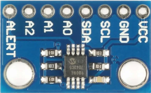
Pin Configuration and Descriptions
The MCP9808 is typically available in an 8-pin package. Below is the pinout and description:
| Pin Number | Pin Name | Description |
|---|---|---|
| 1 | ALERT | Open-drain output for temperature alert |
| 2 | A2 | Address selection bit 2 |
| 3 | A1 | Address selection bit 1 |
| 4 | A0 | Address selection bit 0 |
| 5 | GND | Ground |
| 6 | SCL | I2C clock input |
| 7 | SDA | I2C data input/output |
| 8 | VDD | Power supply (2.7V to 5.5V) |
Usage Instructions
The MCP9808 is easy to integrate into a circuit, thanks to its I2C interface and programmable features. Below are the steps and considerations for using the MCP9808.
Connecting the MCP9808
- Power Supply: Connect the VDD pin to a 2.7V to 5.5V power source and the GND pin to ground.
- I2C Interface: Connect the SCL and SDA pins to the corresponding I2C clock and data lines of your microcontroller. Use pull-up resistors (typically 4.7 kΩ) on both lines.
- Address Selection: Use the A0, A1, and A2 pins to configure the I2C address. These pins can be connected to VDD or GND to set the address.
- Alert Pin: If using the alert function, connect the ALERT pin to your microcontroller or an external circuit. A pull-up resistor may be required.
Example Code for Arduino UNO
Below is an example of how to use the MCP9808 with an Arduino UNO. This code reads the temperature and prints it to the Serial Monitor.
#include <Wire.h>
#include "Adafruit_MCP9808.h"

// Create an MCP9808 object
Adafruit_MCP9808 tempsensor = Adafruit_MCP9808();

void setup() {
  Serial.begin(9600); // Initialize serial communication at 9600 baud
  Serial.println("MCP9808 Temperature Sensor Test");

  // Initialize the I2C interface and check sensor connection
  if (!tempsensor.begin(0x18)) {
    // 0x18 is the default I2C address for MCP9808
    Serial.println("Couldn't find MCP9808! Check wiring.");
    while (1); // Halt execution if sensor is not found
  }

  // Set temperature alert limits (optional)
  tempsensor.setHighTemp(30.0); // Set high temperature limit to 30°C
  tempsensor.setLowTemp(10.0);  // Set low temperature limit to 10°C
  tempsensor.setCriticalTemp(40.0); // Set critical temperature to 40°C
}

void loop() {
  // Read temperature in Celsius
  float tempC = tempsensor.readTempC();

  // Print temperature to Serial Monitor
  Serial.print("Temperature: ");
  Serial.print(tempC);
  Serial.println(" °C");

  delay(1000); // Wait 1 second before the next reading
}
Important Considerations
- I2C Address: The MCP9808's I2C address is determined by the A0, A1, and A2 pins. Ensure the address does not conflict with other devices on the I2C bus.
- Pull-Up Resistors: Use appropriate pull-up resistors on the SDA and SCL lines to ensure proper I2C communication.
- Alert Function: Configure the alert function as needed for your application. The alert pin is open-drain and may require a pull-up resistor.
Troubleshooting and FAQs
Common Issues
Sensor Not Detected on I2C Bus
- Cause: Incorrect wiring or I2C address mismatch.
- Solution: Verify the connections and ensure the A0, A1, and A2 pins are set correctly for the desired I2C address.
Inaccurate Temperature Readings
- Cause: External heat sources or poor placement of the sensor.
- Solution: Place the sensor away from heat sources and ensure good thermal contact with the environment.
Alert Pin Not Functioning
- Cause: Incorrect configuration of temperature thresholds or missing pull-up resistor.
- Solution: Verify the threshold settings and ensure a pull-up resistor is connected to the ALERT pin.
FAQs
Q: Can the MCP9808 operate at 3.3V?
A: Yes, the MCP9808 operates within a supply voltage range of 2.7V to 5.5V, making it compatible with 3.3V systems.
Q: How do I change the resolution of the temperature readings?
A: The resolution can be configured by writing to the resolution register. Refer to the MCP9808 datasheet for details on register settings.
Q: What happens if the temperature exceeds the critical limit?
A: If the temperature exceeds the critical limit, the ALERT pin will be activated (if configured). This can be used to trigger an interrupt or external circuit.
Q: Can I use multiple MCP9808 sensors on the same I2C bus?
A: Yes, up to 8 MCP9808 sensors can be used on the same I2C bus by configuring the A0, A1, and A2 pins to set unique addresses.