How to Use ESP32-S3 Zero: Examples, Pinouts, and Specs
Introduction
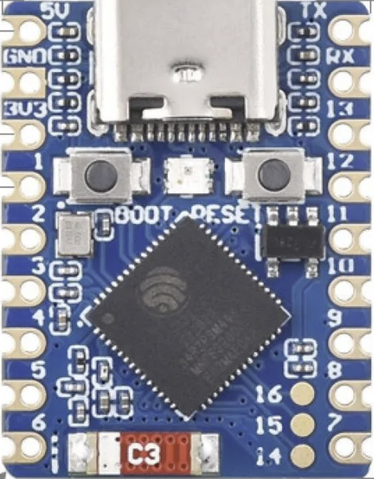
The ESP32-S3 Zero is a low-power system on a chip (SoC) with integrated Wi-Fi and Bluetooth capabilities, designed specifically for Internet of Things (IoT) applications. It features a dual-core Xtensa LX7 processor, ample GPIO pins, and support for a wide range of peripherals, making it an excellent choice for embedded projects. Its advanced features, such as AI acceleration and low-power modes, make it suitable for applications like smart home devices, wearables, and industrial automation.
Explore Projects Built with ESP32-S3 Zero


Explore Projects Built with ESP32-S3 Zero
Common Applications and Use Cases
- Smart home devices (e.g., smart lights, thermostats)
- Wearable technology
- Industrial IoT systems
- AI and machine learning applications
- Wireless sensor networks
- Robotics and automation
Technical Specifications
The ESP32-S3 Zero is packed with features that make it versatile and powerful for a variety of applications. Below are its key technical specifications:
Key Technical Details
- Processor: Dual-core Xtensa LX7, up to 240 MHz
- Memory: 512 KB SRAM, 384 KB ROM, and external PSRAM support
- Wireless Connectivity:
- Wi-Fi: 802.11 b/g/n (2.4 GHz)
- Bluetooth: Bluetooth 5.0 (LE)
- GPIO Pins: 45 (multiplexed with other functions)
- Peripherals: SPI, I2C, UART, ADC, DAC, PWM, I2S, RMT
- AI Acceleration: Vector instructions for machine learning
- Operating Voltage: 3.3V
- Power Consumption: Ultra-low-power modes available
- Package: QFN48 (7x7 mm)
Pin Configuration and Descriptions
The ESP32-S3 Zero has a rich set of GPIO pins and peripherals. Below is a table summarizing the key pins and their functions:
| Pin Name | Function | Description |
|---|---|---|
| GPIO0 | Boot Mode / GPIO | Used for boot mode selection or general-purpose I/O. |
| GPIO1-45 | General Purpose I/O | Configurable as digital I/O, ADC, DAC, PWM, or other peripheral functions. |
| EN | Enable | Chip enable pin. Pull high to enable the chip. |
| 3V3 | Power Supply | 3.3V power input. |
| GND | Ground | Ground connection. |
| TXD0, RXD0 | UART0 TX/RX | Default UART for serial communication. |
| SCL, SDA | I2C Clock and Data | I2C communication pins. |
| SPI_CLK, SPI_MOSI, SPI_MISO, SPI_CS | SPI Interface | SPI clock, data in, data out, and chip select pins. |
| ADC1_x, ADC2_x | Analog Inputs | ADC channels for analog-to-digital conversion. |
| DAC1, DAC2 | Digital-to-Analog Converter | DAC output pins for generating analog signals. |
Note: Some GPIO pins are multiplexed with other functions. Refer to the ESP32-S3 datasheet for detailed pin mapping.
Usage Instructions
The ESP32-S3 Zero is versatile and can be used in a variety of circuits. Below are the steps to get started and important considerations:
How to Use the ESP32-S3 Zero in a Circuit
- Power the Module: Connect the 3.3V pin to a regulated 3.3V power supply and GND to ground.
- Connect GPIO Pins: Use the GPIO pins for digital I/O, ADC, DAC, or other peripheral functions as needed.
- Programming: Use the UART0 (TXD0/RXD0) pins or USB interface to upload code to the ESP32-S3 Zero.
- Wi-Fi and Bluetooth: Configure the wireless settings in your code to enable Wi-Fi or Bluetooth communication.
Important Considerations and Best Practices
- Voltage Levels: Ensure all GPIO pins operate at 3.3V logic levels. Use level shifters if interfacing with 5V devices.
- Power Supply: Use a stable and clean 3.3V power source to avoid noise and instability.
- Boot Mode: Pull GPIO0 low during power-up to enter bootloader mode for programming.
- Peripheral Configuration: Configure the pins properly in your code to avoid conflicts between peripherals.
Example Code for Arduino UNO Integration
The ESP32-S3 Zero can be programmed using the Arduino IDE. Below is an example of how to connect the ESP32-S3 Zero to a Wi-Fi network:
#include <WiFi.h> // Include the Wi-Fi library

// Replace with your network credentials
const char* ssid = "Your_SSID";
const char* password = "Your_PASSWORD";

void setup() {
  Serial.begin(115200); // Initialize serial communication
  delay(1000); // Wait for serial monitor to open

  Serial.println("Connecting to Wi-Fi...");
  WiFi.begin(ssid, password); // Start Wi-Fi connection

  while (WiFi.status() != WL_CONNECTED) {
    delay(500); // Wait for connection
    Serial.print(".");
  }

  Serial.println("\nWi-Fi connected!");
  Serial.print("IP Address: ");
  Serial.println(WiFi.localIP()); // Print the device's IP address
}

void loop() {
  // Add your main code here
}
Note: Install the ESP32 board package in the Arduino IDE before uploading the code.
Troubleshooting and FAQs
Common Issues and Solutions
ESP32-S3 Zero Not Responding
- Cause: Incorrect power supply or wiring.
- Solution: Ensure the module is powered with a stable 3.3V supply and all connections are secure.
Wi-Fi Connection Fails
- Cause: Incorrect SSID or password.
- Solution: Double-check the network credentials in your code.
Cannot Upload Code
- Cause: Boot mode not enabled.
- Solution: Pull GPIO0 low during power-up to enter bootloader mode.
GPIO Pin Not Working
- Cause: Pin conflict or incorrect configuration.
- Solution: Verify the pin's function and ensure it is not being used by another peripheral.
FAQs
Q: Can the ESP32-S3 Zero operate on 5V?
- A: No, the ESP32-S3 Zero operates at 3.3V. Use a level shifter for 5V devices.
Q: How do I reset the ESP32-S3 Zero?
- A: Pull the EN pin low momentarily to reset the module.
Q: Can I use the ESP32-S3 Zero for AI applications?
- A: Yes, the ESP32-S3 Zero supports vector instructions for AI and machine learning tasks.
Q: What is the maximum range of Wi-Fi?
- A: The range depends on environmental factors but typically extends up to 100 meters in open space.
By following this documentation, you can effectively integrate the ESP32-S3 Zero into your projects and troubleshoot common issues.