How to Use Relay protection: Examples, Pinouts, and Specs
Introduction
A relay protection device is a critical component in electrical systems designed to detect faults and isolate affected sections. By doing so, it ensures the safety of the system, prevents damage to equipment, and minimizes downtime. Relay protection devices are widely used in power distribution networks, industrial automation, and renewable energy systems to safeguard electrical infrastructure.
Explore Projects Built with Relay protection


Explore Projects Built with Relay protection
Common Applications and Use Cases
- Power transmission and distribution systems
- Industrial machinery and automation
- Renewable energy systems (e.g., solar and wind farms)
- Motor protection in industrial setups
- Overcurrent, overvoltage, and short-circuit protection
Technical Specifications
Below are the key technical details for a typical relay protection device. Specifications may vary depending on the model and manufacturer.
General Specifications
| Parameter | Value |
|---|---|
| Operating Voltage Range | 24V DC to 240V AC |
| Current Rating | 5A to 30A |
| Response Time | < 20 ms |
| Contact Configuration | SPDT (Single Pole Double Throw) or DPDT (Double Pole Double Throw) |
| Insulation Resistance | > 100 MΩ |
| Operating Temperature | -20°C to 70°C |
| Dielectric Strength | 2 kV AC for 1 minute |
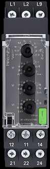
Pin Configuration and Descriptions
| Pin Number | Pin Name | Description |
|---|---|---|
| 1 | Coil (+) | Positive terminal of the relay coil |
| 2 | Coil (-) | Negative terminal of the relay coil |
| 3 | Common (COM) | Common terminal for the switching contacts |
| 4 | Normally Open (NO) | Contact that remains open until the relay is activated |
| 5 | Normally Closed (NC) | Contact that remains closed until the relay is activated |
Usage Instructions
How to Use the Component in a Circuit
- Power the Relay Coil: Connect the coil terminals (Pin 1 and Pin 2) to a suitable power source within the operating voltage range.
- Connect the Load:
- For devices that should turn on when the relay is activated, connect the load to the
NO(Normally Open) terminal andCOM(Common) terminal. - For devices that should turn off when the relay is activated, connect the load to the
NC(Normally Closed) terminal andCOMterminal.
- For devices that should turn on when the relay is activated, connect the load to the
- Control the Relay: Use a microcontroller, such as an Arduino, or a control circuit to activate the relay by energizing the coil.
Important Considerations and Best Practices
- Diode Protection: Always connect a flyback diode across the relay coil to protect the circuit from voltage spikes when the relay is de-energized.
- Current Rating: Ensure the relay's current rating matches or exceeds the load's current requirements.
- Isolation: Use optocouplers or isolation circuits when interfacing the relay with sensitive microcontrollers.
- Testing: Test the relay in a controlled environment before deploying it in critical systems.
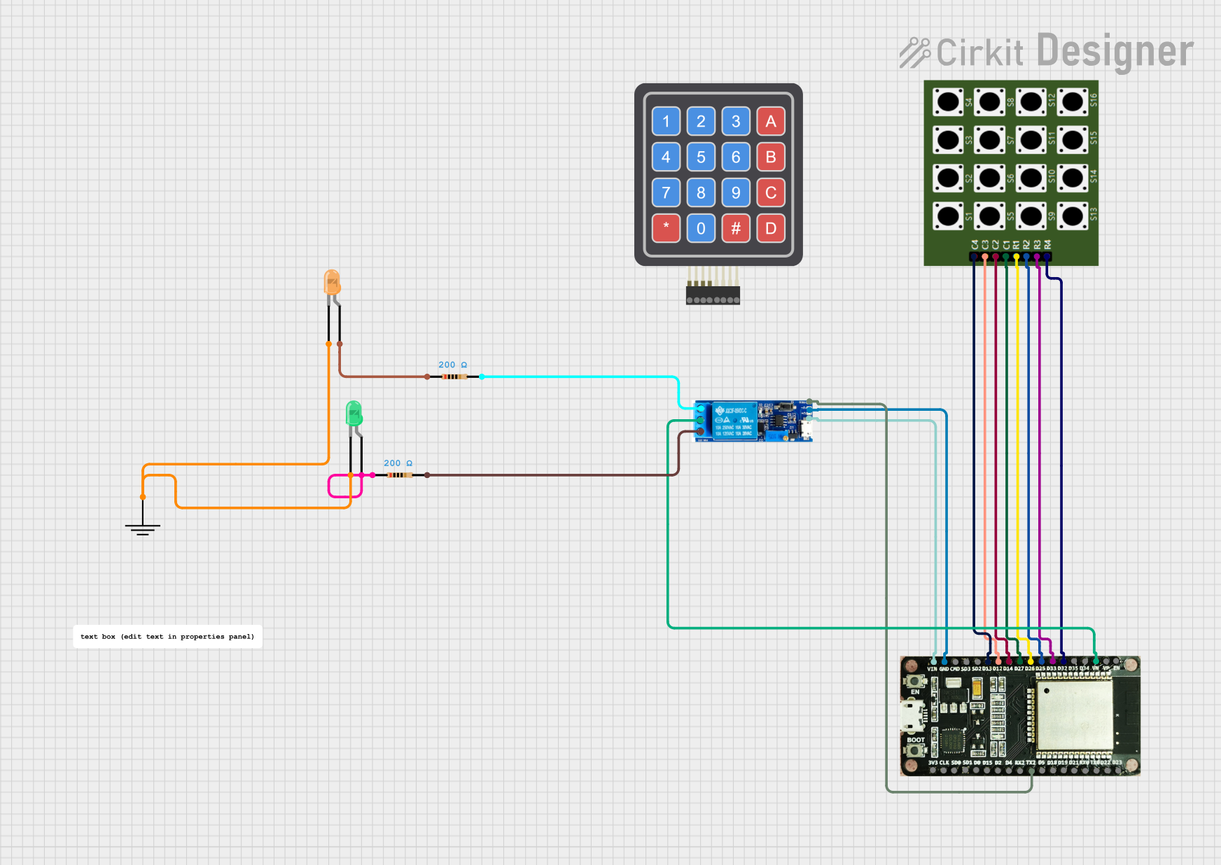
Example: Connecting a Relay to an Arduino UNO
Below is an example of how to control a relay using an Arduino UNO.
// Example: Controlling a relay with Arduino UNO
// Pin 7 is connected to the relay module's control pin

const int relayPin = 7; // Define the pin connected to the relay module

void setup() {
  pinMode(relayPin, OUTPUT); // Set the relay pin as an output
  digitalWrite(relayPin, LOW); // Ensure the relay is off at startup
}

void loop() {
  digitalWrite(relayPin, HIGH); // Turn the relay on
  delay(1000); // Keep the relay on for 1 second
  digitalWrite(relayPin, LOW); // Turn the relay off
  delay(1000); // Keep the relay off for 1 second
}
Troubleshooting and FAQs
Common Issues and Solutions
Relay Not Activating
- Cause: Insufficient voltage or current to the relay coil.
- Solution: Verify the power supply voltage and current match the relay's specifications.
Relay Stuck in One State
- Cause: Mechanical failure or damaged contacts.
- Solution: Replace the relay if it is physically damaged or worn out.
Voltage Spikes Damaging the Circuit
- Cause: Lack of a flyback diode across the relay coil.
- Solution: Install a flyback diode (e.g., 1N4007) across the coil terminals.
Microcontroller Resetting When Relay Activates
- Cause: Electromagnetic interference (EMI) or insufficient power supply decoupling.
- Solution: Add decoupling capacitors near the microcontroller and ensure proper grounding.
FAQs
Q: Can I use a relay protection device for AC and DC loads?
A: Yes, most relay protection devices can handle both AC and DC loads, but ensure the relay's voltage and current ratings are suitable for the specific load.
Q: How do I know if my relay is working?
A: You can hear a clicking sound when the relay switches states. Additionally, you can measure continuity between the COM and NO or NC terminals to verify operation.
Q: What is the purpose of the flyback diode?
A: The flyback diode protects the circuit from voltage spikes generated when the relay coil is de-energized, preventing damage to other components.
Q: Can I use a relay without a microcontroller?
A: Yes, you can control a relay using a manual switch, timer circuit, or other control mechanisms, as long as the coil is powered appropriately.