How to Use J3Y NPN: Examples, Pinouts, and Specs
Introduction
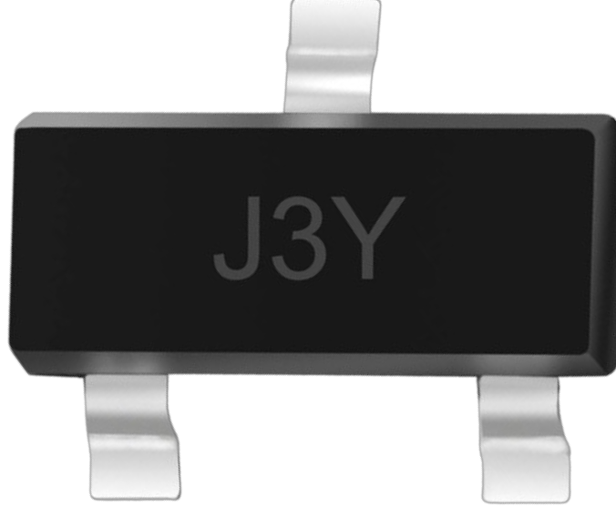
The J3Y NPN is a type of bipolar junction transistor (BJT) that is widely used for amplification and switching applications. It features three layers of semiconductor material and operates by controlling the current flow between the collector and emitter terminals based on the input current at the base terminal. This small-signal transistor is commonly found in low-power electronic circuits due to its compact size and reliable performance.
Explore Projects Built with J3Y NPN

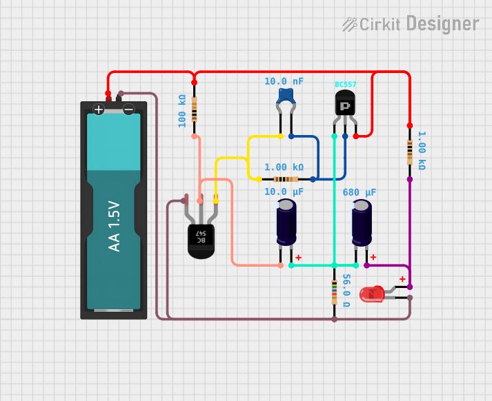
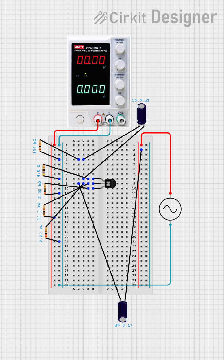
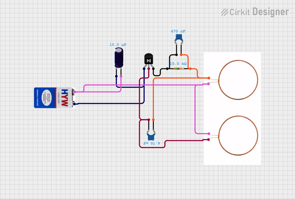
Explore Projects Built with J3Y NPN
Common Applications and Use Cases
- Signal amplification in audio and RF circuits
- Switching small loads in digital and analog circuits
- Used in logic circuits and microcontroller-based projects
- General-purpose low-power applications
Technical Specifications
Below are the key technical details of the J3Y NPN transistor:
| Parameter | Value |
|---|---|
| Transistor Type | NPN |
| Maximum Collector-Emitter Voltage (Vce) | 50V |
| Maximum Collector-Base Voltage (Vcb) | 60V |
| Maximum Emitter-Base Voltage (Veb) | 5V |
| Maximum Collector Current (Ic) | 150mA |
| Power Dissipation (Ptot) | 200mW |
| DC Current Gain (hFE) | 120 to 400 |
| Transition Frequency (ft) | 150 MHz |
| Package Type | SOT-23 |
Pin Configuration and Descriptions
The J3Y NPN transistor is housed in a compact SOT-23 package with three pins. The pin configuration is as follows:
| Pin Number | Pin Name | Description |
|---|---|---|
| 1 | Base (B) | Controls the transistor's operation by |
| regulating the current flow between the | ||
| collector and emitter. | ||
| 2 | Emitter (E) | The terminal through which current exits |
| the transistor. | ||
| 3 | Collector (C) | The terminal through which current enters |
| the transistor. |
Usage Instructions
How to Use the J3Y NPN in a Circuit
Determine the Operating Region: The J3Y NPN transistor can operate in three regions:
- Cutoff Region: The transistor is OFF, and no current flows between the collector and emitter.
- Active Region: The transistor amplifies the input signal.
- Saturation Region: The transistor is fully ON, acting as a closed switch.
Connect the Pins:
- Connect the Base pin to the input signal through a current-limiting resistor (typically 1kΩ to 10kΩ).
- Connect the Collector pin to the positive voltage supply (Vcc) through the load.
- Connect the Emitter pin to ground.
Calculate the Base Resistor:
- Use the formula ( R_B = \frac{V_{in} - V_{BE}}{I_B} ), where:
- ( V_{in} ) is the input voltage.
- ( V_{BE} ) is the base-emitter voltage (typically 0.7V for silicon BJTs).
- ( I_B ) is the base current, which can be calculated as ( I_B = \frac{I_C}{h_{FE}} ).
- Use the formula ( R_B = \frac{V_{in} - V_{BE}}{I_B} ), where:
Test the Circuit: Apply the input signal to the base and observe the output at the collector.
Important Considerations and Best Practices
- Always use a current-limiting resistor at the base to prevent excessive current flow.
- Ensure the collector current does not exceed the maximum rating of 150mA.
- Operate the transistor within its voltage and power dissipation limits to avoid damage.
- For switching applications, ensure the transistor is driven into full saturation for optimal performance.
Example: Using J3Y NPN with Arduino UNO
The J3Y NPN transistor can be used to control a small load, such as an LED, with an Arduino UNO. Below is an example circuit and code:
Circuit Connections
- Connect the Base pin of the J3Y to Arduino digital pin 9 through a 1kΩ resistor.
- Connect the Emitter pin to ground.
- Connect the Collector pin to one terminal of the LED. Connect the other terminal of the LED to a 220Ω resistor, and then to the positive voltage supply (5V).
Arduino Code
// Define the pin connected to the transistor's base
const int transistorBasePin = 9;

void setup() {
  // Set the transistor base pin as an output
  pinMode(transistorBasePin, OUTPUT);
}

void loop() {
  // Turn the LED ON by driving the transistor into saturation
  digitalWrite(transistorBasePin, HIGH);
  delay(1000); // Keep the LED ON for 1 second

  // Turn the LED OFF by cutting off the base current
  digitalWrite(transistorBasePin, LOW);
  delay(1000); // Keep the LED OFF for 1 second
}
Troubleshooting and FAQs
Common Issues and Solutions
The transistor is not switching ON:
- Ensure the base resistor value is appropriate for the input signal and load.
- Verify that the base-emitter voltage (( V_{BE} )) is at least 0.7V.
The transistor overheats:
- Check that the collector current does not exceed 150mA.
- Ensure the power dissipation is within the 200mW limit.
The load is not functioning properly:
- Verify the connections and ensure the load is within the transistor's current handling capacity.
- Check for loose or incorrect wiring.
The transistor is damaged:
- Ensure the voltage and current ratings are not exceeded.
- Avoid reverse polarity connections.
FAQs
Q1: Can the J3Y NPN transistor be used for high-power applications?
A1: No, the J3Y is a low-power transistor with a maximum collector current of 150mA and power dissipation of 200mW. For high-power applications, consider using a power transistor.
Q2: What is the purpose of the base resistor?
A2: The base resistor limits the current flowing into the base to prevent damage to the transistor and ensure proper operation.
Q3: Can the J3Y NPN transistor be used with a 3.3V microcontroller?
A3: Yes, the J3Y can be used with a 3.3V microcontroller, provided the base-emitter voltage (( V_{BE} )) is sufficient to turn the transistor ON and the load requirements are within the transistor's limits.