Cirkit Designer Logo
Cirkit Designer
Your all-in-one circuit design IDE
Home / 
Component Documentation

How to Use rxn433mhz: Examples, Pinouts, and Specs

Image of rxn433mhz
Cirkit Designer LogoDesign with rxn433mhz in Cirkit Designer

Introduction

The RXN-433MHz RF Receiver Module is a compact and low-power radio frequency receiver that operates at the 433MHz frequency, commonly used for short-range wireless communication in various applications. This module is widely used in remote control systems, telemetry, wireless alarm systems, and various DIY projects. It is designed to receive coded signals from a compatible 433MHz RF transmitter and can be easily interfaced with microcontrollers such as Arduino, Raspberry Pi, and others.

Explore Projects Built with rxn433mhz

Use Cirkit Designer to design, explore, and prototype these projects online. Some projects support real-time simulation. Click "Open Project" to start designing instantly!
Arduino UNO with 433MHz RF Module for Wireless Communication
Image of Receiver: A project utilizing rxn433mhz in a practical application
This circuit consists of an Arduino UNO connected to an RXN433MHz radio frequency module. The Arduino provides 5V power and ground to the RF module and is configured to communicate with it via digital pin D11. Additionally, a multimeter is connected with alligator clip cables to measure the voltage supplied to the RF module.
Cirkit Designer LogoOpen Project in Cirkit Designer
433 MHz RF Transmitter and Receiver with Arduino UNO for Wireless Communication
Image of Wireless Communication: A project utilizing rxn433mhz in a practical application
This circuit consists of two Arduino UNO microcontrollers, each connected to an RF 433 MHz Transmitter and a 433 MHz RF Receiver Module. The setup allows for wireless communication between the two Arduinos, enabling them to send and receive data over a 433 MHz RF link.
Cirkit Designer LogoOpen Project in Cirkit Designer
Arduino-Based RF-Controlled MOSFET Switch with Battery Power
Image of radio shit: A project utilizing rxn433mhz in a practical application
This circuit consists of two Arduino UNOs communicating wirelessly using 433MHz RF modules. One Arduino sends 'yes' or 'no' signals via an RF transmitter, while the other Arduino receives these signals through an RF receiver and controls a MOSFET to switch a 12V power source on or off based on the received signal.
Cirkit Designer LogoOpen Project in Cirkit Designer
433 MHz RF Transmitter and Receiver with Arduino Uno for Wireless LED Control
Image of rf module up: A project utilizing rxn433mhz in a practical application
This circuit consists of two Arduino Uno R3 microcontrollers communicating wirelessly using 433 MHz RF modules. One Arduino is connected to an RF transmitter to send data, while the other Arduino is connected to an RF receiver to receive data and control an LED based on the received signal.
Cirkit Designer LogoOpen Project in Cirkit Designer

Explore Projects Built with rxn433mhz

Use Cirkit Designer to design, explore, and prototype these projects online. Some projects support real-time simulation. Click "Open Project" to start designing instantly!
Image of Receiver: A project utilizing rxn433mhz in a practical application
Arduino UNO with 433MHz RF Module for Wireless Communication
This circuit consists of an Arduino UNO connected to an RXN433MHz radio frequency module. The Arduino provides 5V power and ground to the RF module and is configured to communicate with it via digital pin D11. Additionally, a multimeter is connected with alligator clip cables to measure the voltage supplied to the RF module.
Cirkit Designer LogoOpen Project in Cirkit Designer
Image of Wireless Communication: A project utilizing rxn433mhz in a practical application
433 MHz RF Transmitter and Receiver with Arduino UNO for Wireless Communication
This circuit consists of two Arduino UNO microcontrollers, each connected to an RF 433 MHz Transmitter and a 433 MHz RF Receiver Module. The setup allows for wireless communication between the two Arduinos, enabling them to send and receive data over a 433 MHz RF link.
Cirkit Designer LogoOpen Project in Cirkit Designer
Image of radio shit: A project utilizing rxn433mhz in a practical application
Arduino-Based RF-Controlled MOSFET Switch with Battery Power
This circuit consists of two Arduino UNOs communicating wirelessly using 433MHz RF modules. One Arduino sends 'yes' or 'no' signals via an RF transmitter, while the other Arduino receives these signals through an RF receiver and controls a MOSFET to switch a 12V power source on or off based on the received signal.
Cirkit Designer LogoOpen Project in Cirkit Designer
Image of rf module up: A project utilizing rxn433mhz in a practical application
433 MHz RF Transmitter and Receiver with Arduino Uno for Wireless LED Control
This circuit consists of two Arduino Uno R3 microcontrollers communicating wirelessly using 433 MHz RF modules. One Arduino is connected to an RF transmitter to send data, while the other Arduino is connected to an RF receiver to receive data and control an LED based on the received signal.
Cirkit Designer LogoOpen Project in Cirkit Designer

Technical Specifications

Key Technical Details

  • Operating Frequency: 433MHz
  • Supply Voltage (Vcc): 3.3V to 5V DC
  • Current Consumption: 5mA (typical) at 5V
  • Sensitivity: -105dBm (typical)
  • Modulation: ASK/OOK
  • Operating Temperature: -20°C to +70°C

Pin Configuration and Descriptions

Pin Number Pin Name Description
1 GND Ground, connected to the system ground
2 DATA Data output, delivers the demodulated data
3 Vcc Supply voltage, 3.3V to 5V DC
4 ANT Antenna connection, for the 433MHz signal

Usage Instructions

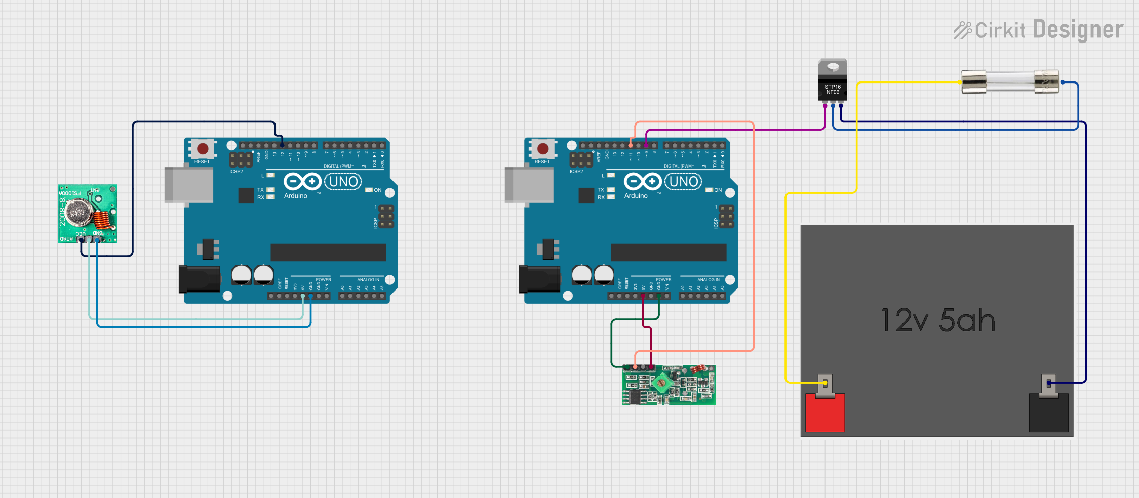
Interfacing with an Arduino UNO

  1. Connecting the Module:

    • Connect the GND pin of the RXN-433MHz module to the GND pin on the Arduino.
    • Connect the DATA pin of the module to a digital I/O pin on the Arduino (e.g., D2).
    • Connect the Vcc pin of the module to the 5V output on the Arduino.
    • Attach a 17cm wire to the ANT pin to act as an antenna.
  2. Arduino Sketch:

    • Use the RadioHead or rc-switch library for handling the RF signals.
    • Initialize the RF receiver object and specify the pin connected to the DATA pin of the module.
    • Implement a callback function to handle the received data.
#include <RH_ASK.h>
// Include RadioHead Amplitude Shift Keying Library

RH_ASK rf_receiver;
// Create Amplitude Shift Keying Object

void setup()
{
    Serial.begin(9600); // Initialize Serial Monitor
    if (!rf_receiver.init())
        Serial.println("init failed");
    // Initialize ASK Object
}

void loop()
{
    uint8_t buf[RH_ASK_MAX_MESSAGE_LEN];
    uint8_t buflen = sizeof(buf);

    if (rf_receiver.recv(buf, &buflen)) // Check if data received
    {
        int i;
        Serial.print("Message Received: ");
        for (i = 0; i < buflen; i++)
        {
            Serial.print((char)buf[i]);
        }
        Serial.println();
    }
}

Important Considerations and Best Practices

  • Ensure that the antenna length is approximately 17cm for optimal reception.
  • Place the module away from metal objects and noise sources for better performance.
  • Use a decoupling capacitor (e.g., 100nF) between Vcc and GND close to the module to filter out power supply noise.

Troubleshooting and FAQs

Common Issues

  • No Data Received: Ensure the transmitter and receiver are on the same frequency and that the antenna is properly connected.
  • Intermittent Reception: Check for obstacles or interference sources near the module. Adjust the antenna position or length.
  • Noise in Received Data: Add a decoupling capacitor and ensure the power supply is stable.

Solutions and Tips

  • Improving Range: Increase the height of the antenna or use a higher gain antenna.
  • Filtering Noise: Implement software filtering techniques to distinguish between noise and actual data.
  • Testing: Use a known good transmitter to test the receiver functionality.

FAQs

Q: Can the RXN-433MHz module be used with a 3.3V system? A: Yes, the module can operate with a supply voltage as low as 3.3V.

Q: What is the maximum range of the module? A: The range depends on many factors, including antenna design, but it can typically reach up to 100 meters in open space.

Q: How can I increase the data rate? A: The data rate is limited by the modulation technique and the quality of the signal. For higher data rates, consider using a different module with FSK modulation or a higher frequency band.

Q: Is it necessary to use an external antenna? A: Yes, an external antenna is required for proper operation. A simple wire with a length of 17cm can serve as an adequate antenna for most applications.