How to Use 12v 4 Pin Common Vehicle Relay: Examples, Pinouts, and Specs
Introduction
The 12V 4 Pin Common Vehicle Relay is an electromechanical switch designed to control high-current devices, such as headlights, horns, or fuel pumps, using a low-current signal. It operates at 12 volts, making it ideal for automotive applications. This relay is widely used in vehicles to isolate and protect sensitive control circuits while enabling the operation of high-power loads.
Explore Projects Built with 12v 4 Pin Common Vehicle Relay


Explore Projects Built with 12v 4 Pin Common Vehicle Relay
Common Applications and Use Cases
- Automotive lighting systems (e.g., headlights, fog lights)
- Horn circuits
- Fuel pump control
- Electric fan control
- Power window and door lock systems
- General-purpose switching in 12V DC circuits
Technical Specifications
The following table outlines the key technical details of the 12V 4 Pin Common Vehicle Relay:
| Parameter | Specification |
|---|---|
| Operating Voltage | 12V DC |
| Coil Resistance | ~85 Ohms (typical) |
| Coil Current | ~140 mA |
| Contact Rating | 30A @ 12V DC |
| Contact Configuration | SPST (Single Pole Single Throw) |
| Switching Voltage | Up to 14V DC |
| Operating Temperature | -40°C to +85°C |
| Dimensions | ~28mm x 28mm x 25mm |
Pin Configuration and Descriptions
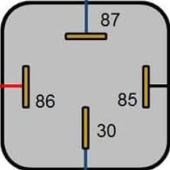
The 12V 4 Pin Common Vehicle Relay has the following pinout:
| Pin Number | Name | Description |
|---|---|---|
| 85 | Coil (-) | Connects to the negative terminal of the control signal (ground). |
| 86 | Coil (+) | Connects to the positive terminal of the control signal (12V DC). |
| 30 | Common | Connects to the power source or load. |
| 87 | Normally Open (NO) | Connects to the load. Closed when the relay is activated. |
Usage Instructions
How to Use the Component in a Circuit
- Identify the Pins: Refer to the pin configuration table to locate pins 85, 86, 30, and 87.
- Connect the Coil:
- Pin 85: Connect to the ground of the control circuit.
- Pin 86: Connect to the positive control signal (e.g., from a switch or microcontroller output).
- Connect the Load:
- Pin 30: Connect to the positive terminal of the power source.
- Pin 87: Connect to the positive terminal of the load (e.g., a motor or light).
- Complete the Circuit: Ensure the load's negative terminal is connected to the ground.
- Activate the Relay: Apply a 12V signal across pins 85 and 86 to energize the coil and close the circuit between pins 30 and 87.
Important Considerations and Best Practices
- Diode Protection: Add a flyback diode across the coil (pins 85 and 86) to protect the control circuit from voltage spikes when the relay is de-energized.
- Current Rating: Ensure the load current does not exceed the relay's contact rating (30A).
- Secure Connections: Use appropriate connectors or soldering to ensure reliable connections, especially in automotive environments.
- Mounting: Use a relay socket or secure the relay in place to prevent vibration-related issues.
Example: Connecting to an Arduino UNO
The 12V 4 Pin Common Vehicle Relay can be controlled by an Arduino UNO using a transistor as an intermediary to handle the relay's coil current. Below is an example circuit and code:
Circuit Setup
- Connect the relay's pin 85 to the collector of an NPN transistor (e.g., 2N2222).
- Connect the emitter of the transistor to ground.
- Connect pin 86 of the relay to a 12V power source.
- Place a flyback diode (e.g., 1N4007) across pins 85 and 86, with the cathode connected to pin 86.
- Connect the base of the transistor to an Arduino digital pin (e.g., pin 7) through a 1kΩ resistor.
- Connect pin 30 of the relay to the 12V power source.
- Connect pin 87 of the relay to the positive terminal of the load.
Arduino Code
// Define the pin connected to the transistor base
const int relayControlPin = 7;

void setup() {
  // Set the relay control pin as an output
  pinMode(relayControlPin, OUTPUT);
}

void loop() {
  // Turn the relay ON
  digitalWrite(relayControlPin, HIGH);
  delay(5000); // Keep the relay ON for 5 seconds

  // Turn the relay OFF
  digitalWrite(relayControlPin, LOW);
  delay(5000); // Keep the relay OFF for 5 seconds
}
Troubleshooting and FAQs
Common Issues and Solutions
Relay Not Activating:
- Cause: Insufficient control voltage or current.
- Solution: Verify that the control signal is 12V and capable of supplying ~140 mA. Use a transistor if controlling with a microcontroller.
Voltage Spikes Damaging the Circuit:
- Cause: Lack of a flyback diode across the relay coil.
- Solution: Install a flyback diode (e.g., 1N4007) across pins 85 and 86.
Load Not Receiving Power:
- Cause: Incorrect wiring of pins 30 and 87.
- Solution: Double-check the connections and ensure the load is properly connected to pin 87.
Relay Overheating:
- Cause: Load current exceeds the relay's contact rating.
- Solution: Use a relay with a higher current rating or reduce the load current.
FAQs
Q: Can I use this relay with a 5V control signal?
A: No, the relay requires a 12V control signal. Use a transistor to step up the control voltage if needed.
Q: Is this relay suitable for AC loads?
A: No, this relay is designed for DC loads only. Use a relay rated for AC if switching AC devices.
Q: Can I use this relay without a flyback diode?
A: It is not recommended. A flyback diode protects the control circuit from voltage spikes and ensures reliable operation.