
How to Use JST-B3P-VH: Examples, Pinouts, and Specs
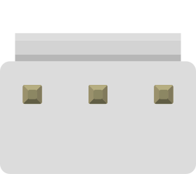
 Design with JST-B3P-VH in Cirkit Designer
Introduction
The JST-B3P-VH is a 3-pin connector manufactured by JST, designed for secure and reliable electrical connections. It features a compact design and a dependable locking mechanism, making it ideal for applications requiring robust power or signal transmission. This connector is widely used in consumer electronics, industrial equipment, and hobbyist projects due to its ease of use and durability.
Explore Projects Built with JST-B3P-VH
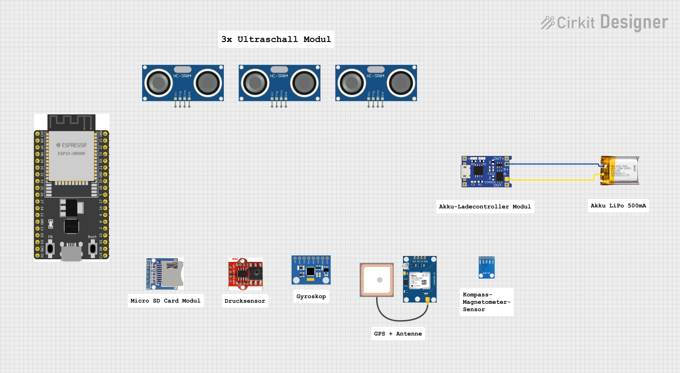 Open Project in Cirkit Designer
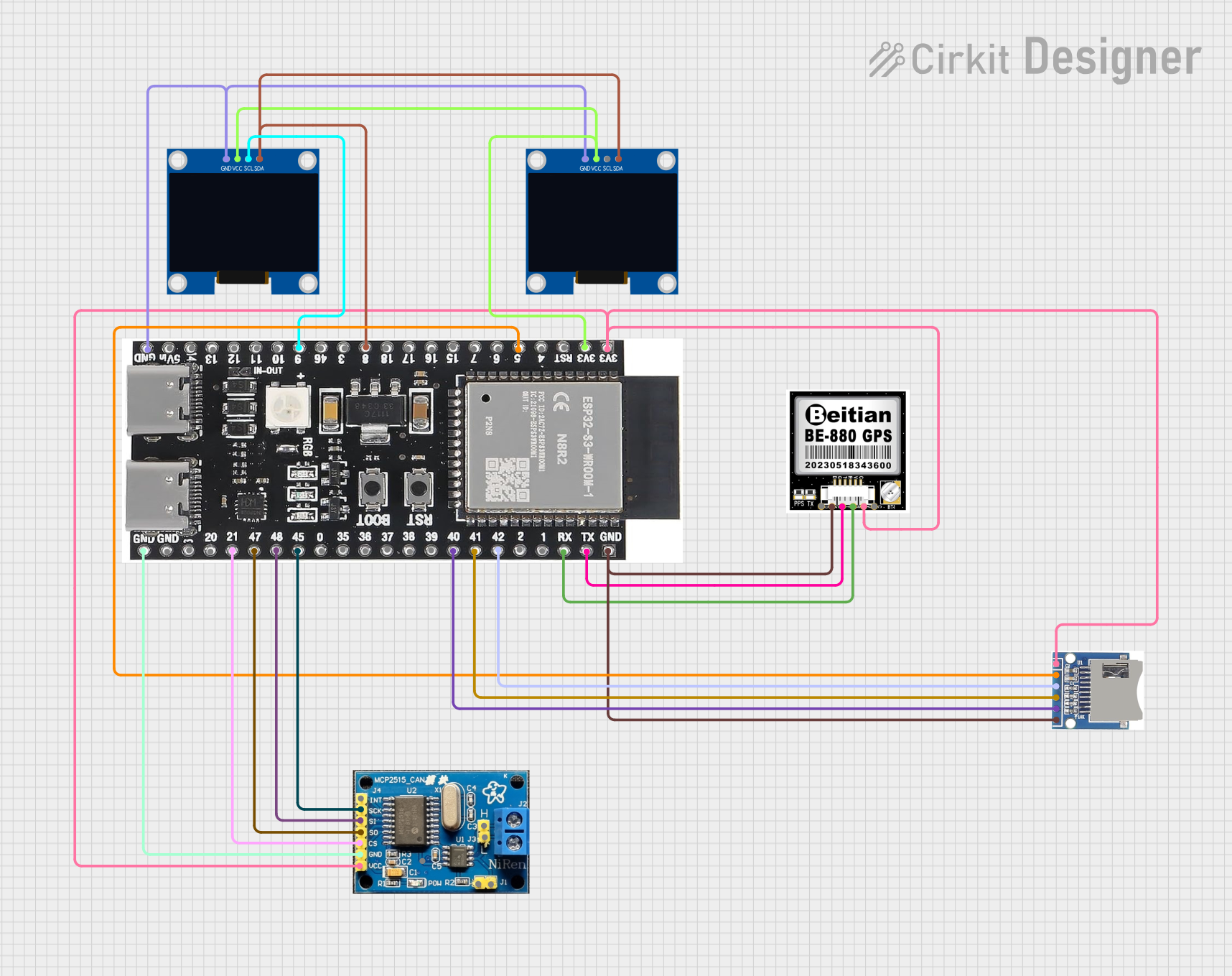 Open Project in Cirkit Designer
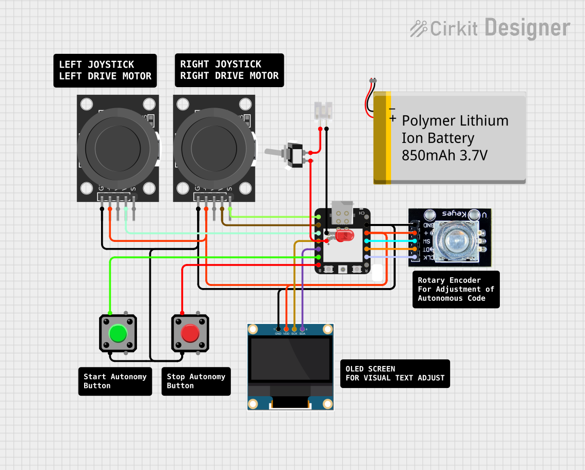 Open Project in Cirkit Designer
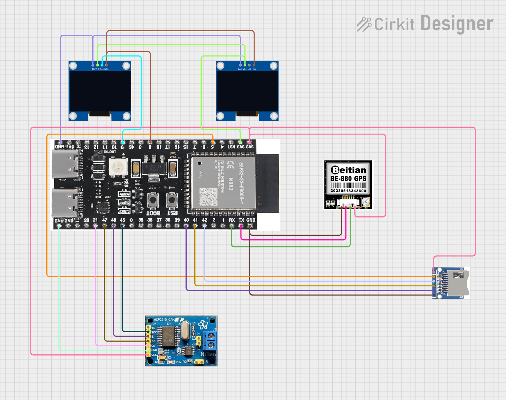 Open Project in Cirkit Designer
Explore Projects Built with JST-B3P-VH
Open Project in Cirkit DesignerOpen Project in Cirkit DesignerOpen Project in Cirkit DesignerOpen Project in Cirkit DesignerCommon Applications
- Power supply connections in electronic devices
- Signal transmission in industrial control systems
- Battery connections in RC vehicles and drones
- DIY electronics and prototyping projects
Technical Specifications
Key Technical Details
| Parameter | Value |
|---|---|
| Manufacturer | JST |
| Part Number | B3P-VH |
| Number of Pins | 3 |
| Connector Type | Wire-to-Board |
| Pitch | 3.96 mm |
| Rated Voltage | 250 V AC/DC |
| Rated Current | 10 A |
| Operating Temperature | -25°C to +85°C |
| Material (Housing) | Nylon 66 (UL94V-0, flame-retardant) |
| Locking Mechanism | Friction lock |
Pin Configuration and Descriptions
The JST-B3P-VH connector has three pins arranged in a single row with a 3.96 mm pitch. Below is the pin configuration:
| Pin Number | Description | Typical Use Case |
|---|---|---|
| 1 | Positive Voltage (+) | Power supply or signal line |
| 2 | Ground (GND) | Common ground connection |
| 3 | Signal/Voltage Line | Additional signal or power |
Usage Instructions
How to Use the JST-B3P-VH in a Circuit
Connector Assembly:
- Use compatible crimp terminals (e.g., JST VHR series) to terminate wires.
- Insert the crimped terminals into the connector housing until they click into place.
- Ensure proper alignment of the terminals to avoid misconnection.
PCB Mounting:
- The JST-B3P-VH mates with a corresponding PCB header (e.g., JST VHR-3N).
- Solder the header onto the PCB, ensuring correct orientation.
Mating and Unmating:
- Align the connector with the header and push until the locking mechanism engages.
- To disconnect, press the locking tab and gently pull the connector away.
Important Considerations and Best Practices
- Wire Selection: Use wires with appropriate gauge (e.g., 18-24 AWG) to handle the rated current.
- Crimping: Use a proper crimping tool to ensure secure and reliable connections.
- Polarity: Double-check the pinout to avoid reversing polarity, which could damage connected components.
- Environmental Conditions: Avoid exposing the connector to temperatures or voltages beyond its rated limits.
Example: Connecting to an Arduino UNO
The JST-B3P-VH can be used to supply power to an Arduino UNO or connect external components. Below is an example of wiring and code for reading a signal from a sensor connected via the JST-B3P-VH.
Wiring Diagram
- Pin 1: Connect to the sensor's VCC (e.g., 5V).
- Pin 2: Connect to GND.
- Pin 3: Connect to the sensor's signal output, which is read by an Arduino input pin (e.g., A0).
Arduino Code Example
// Example code for reading a sensor signal connected via JST-B3P-VH
const int sensorPin = A0; // Pin A0 is connected to the signal line (Pin 3)
int sensorValue = 0;      // Variable to store the sensor reading

void setup() {
  Serial.begin(9600); // Initialize serial communication at 9600 baud
  pinMode(sensorPin, INPUT); // Set the sensor pin as an input
}

void loop() {
  sensorValue = analogRead(sensorPin); // Read the sensor value
  Serial.print("Sensor Value: ");
  Serial.println(sensorValue); // Print the sensor value to the Serial Monitor
  delay(500); // Wait for 500ms before the next reading
}
Troubleshooting and FAQs
Common Issues and Solutions
Loose Connections:
- Issue: The connector feels loose or disconnects easily.
- Solution: Ensure the crimp terminals are properly inserted and locked into the housing. Verify that the mating header is securely soldered to the PCB.
Overheating:
- Issue: The connector becomes warm during operation.
- Solution: Check that the current does not exceed the rated 10 A. Use thicker wires if necessary.
Misalignment:
- Issue: The connector does not mate properly with the header.
- Solution: Verify the orientation of the connector and header. Ensure no debris is obstructing the connection.
Signal Interference:
- Issue: Unstable or noisy signal transmission.
- Solution: Use shielded cables for signal lines and ensure proper grounding.
FAQs
Q1: Can the JST-B3P-VH handle high-frequency signals?
A1: While the connector is primarily designed for power and low-frequency signals, it can handle moderate-frequency signals depending on the application. For high-frequency signals, consider using connectors specifically designed for RF or high-speed data.
Q2: Is the JST-B3P-VH waterproof?
A2: No, the JST-B3P-VH is not waterproof. For outdoor or moisture-prone environments, use a waterproof connector or additional sealing methods.
Q3: Can I use the JST-B3P-VH for battery connections?
A3: Yes, the JST-B3P-VH is commonly used for battery connections in RC vehicles and other devices. Ensure the current and voltage ratings are not exceeded.
Q4: What tools are recommended for crimping?
A4: Use a JST-compatible crimping tool, such as the Engineer PA-09 or similar, to achieve reliable and consistent crimps.
This concludes the documentation for the JST-B3P-VH connector.