How to Use Flex Sensor 2.2": Examples, Pinouts, and Specs

Introduction
The Flex Sensor 2.2" is a resistive sensor that changes its resistance based on the degree of bending or flexing applied to it. This unique property makes it an ideal choice for applications requiring motion, position, or angle detection. The sensor is commonly used in robotics, wearable technology, gaming devices, and medical equipment to measure bending or movement.
Explore Projects Built with Flex Sensor 2.2"
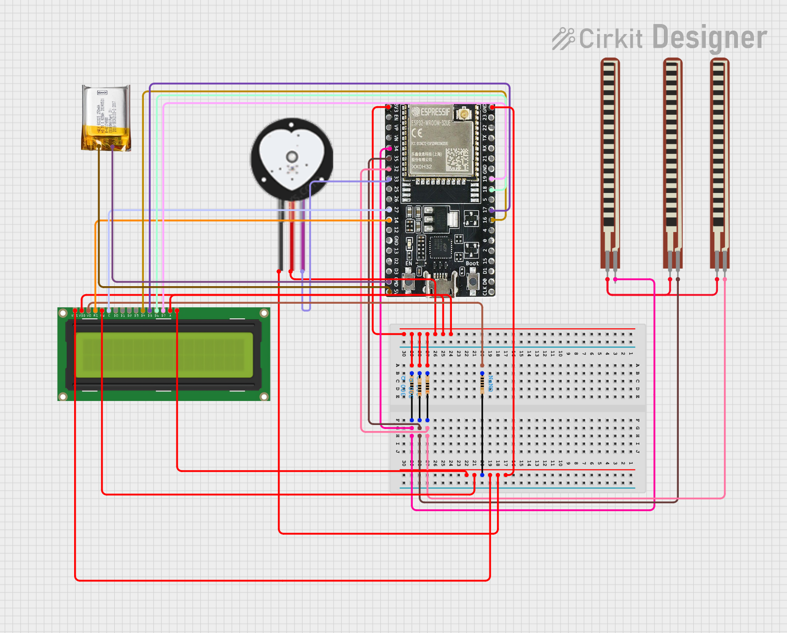
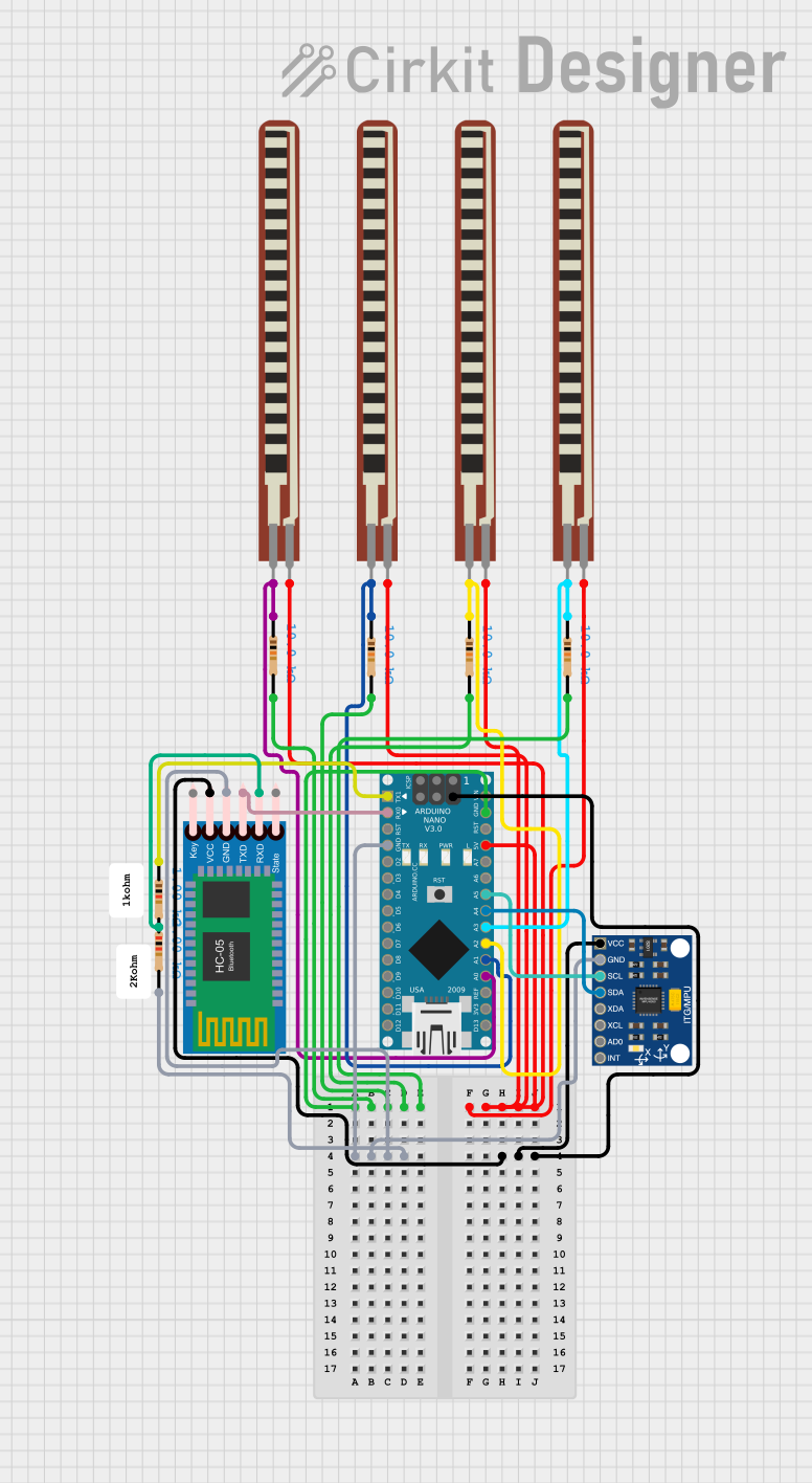
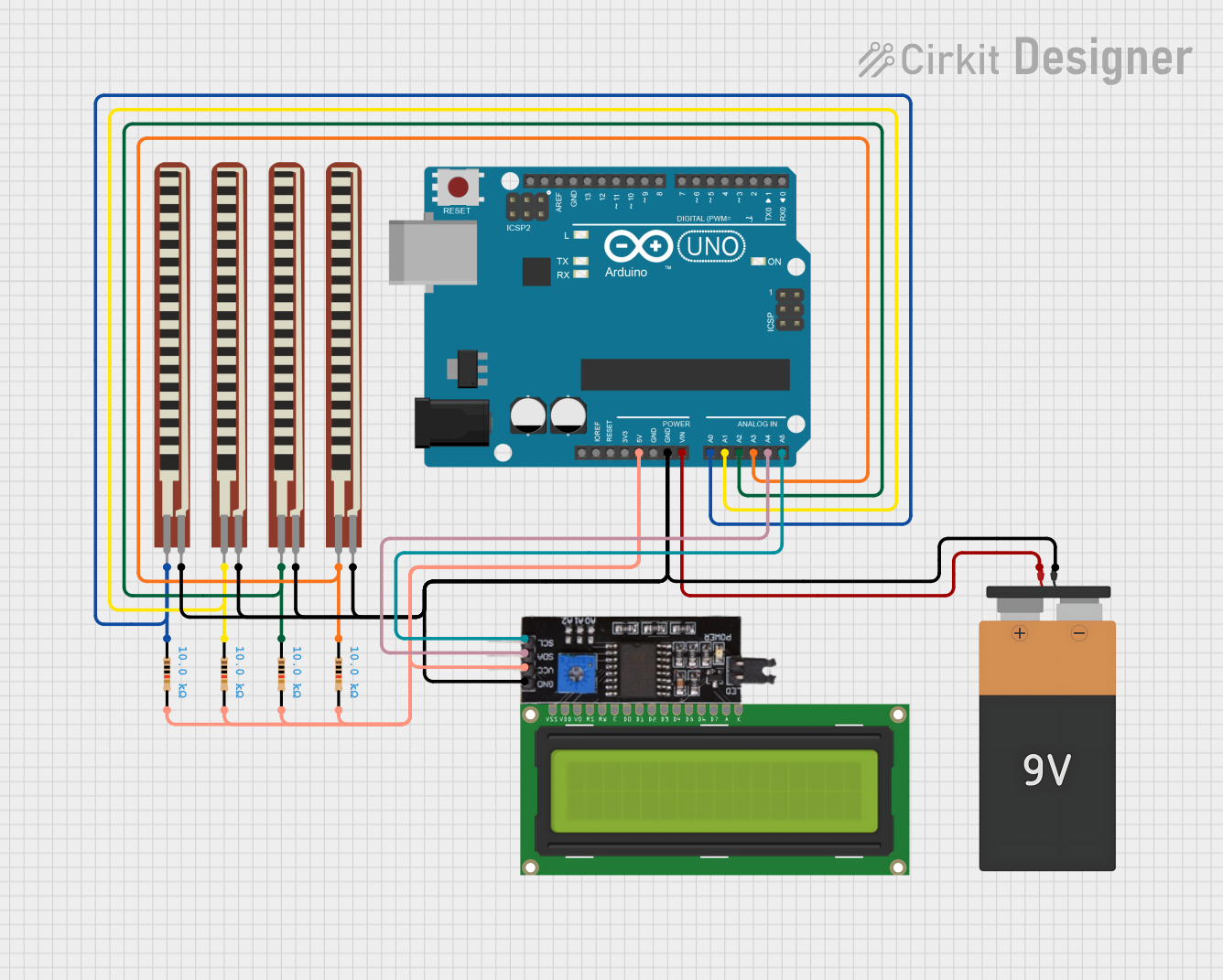
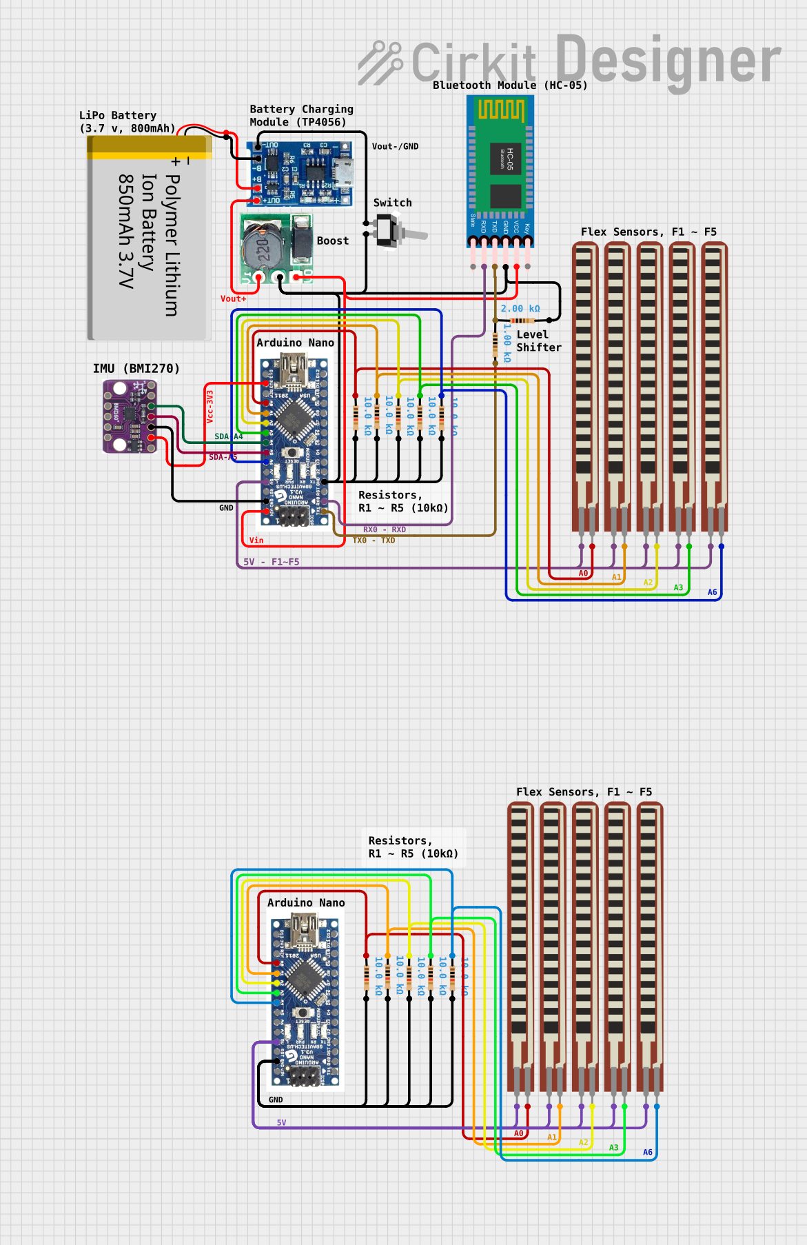
Explore Projects Built with Flex Sensor 2.2"
Common Applications:
- Gesture recognition in wearable devices
- Robotic joint angle measurement
- Gaming controllers for motion sensing
- Prosthetics and medical devices for motion tracking
- Animatronics and interactive art installations
Technical Specifications
The following table outlines the key technical details of the Flex Sensor 2.2":
| Parameter | Value |
|---|---|
| Length | 2.2 inches (55.88 mm) |
| Resistance (Flat State) | ~10 kΩ |
| Resistance (Bent State) | ~20 kΩ to ~70 kΩ (varies) |
| Bend Angle Range | 0° to ~90° |
| Power Rating | 0.5 W (maximum) |
| Operating Voltage | 0 V to 5 V |
| Operating Temperature | -35°C to +80°C |
| Connector Type | Solderable pads or terminals |
Pin Configuration and Descriptions
The Flex Sensor 2.2" has two terminals, as shown below:
| Pin | Description |
|---|---|
| Pin 1 | One end of the resistive element (connect to VCC or signal input) |
| Pin 2 | Other end of the resistive element (connect to GND or signal output) |
Usage Instructions
How to Use the Flex Sensor in a Circuit
Basic Circuit Setup:
- Connect one terminal of the Flex Sensor to a voltage source (e.g., 5V).
- Connect the other terminal to a pull-down resistor (e.g., 10 kΩ) and then to ground (GND).
- The junction between the Flex Sensor and the pull-down resistor serves as the output voltage, which varies with the sensor's resistance.
Reading the Output:
- The output voltage can be read using an analog input pin of a microcontroller (e.g., Arduino UNO).
- As the sensor bends, its resistance increases, causing the output voltage to change proportionally.
Circuit Diagram:
VCC (5V) ---- Flex Sensor ----+---- Analog Input (A0)
                              |
                              R (10 kΩ)
                              |
                             GND
Important Considerations and Best Practices
- Avoid bending the sensor beyond its specified range (90°) to prevent damage.
- Use a resistor value that matches the sensor's resistance range for optimal voltage output.
- Ensure the sensor is securely mounted to avoid false readings due to vibrations or loose connections.
- For long-term use, consider adding strain relief to the sensor's terminals to prevent wear and tear.
Example Code for Arduino UNO
The following code demonstrates how to read the Flex Sensor's output using an Arduino UNO and display the results in the Serial Monitor:
// Define the analog pin connected to the Flex Sensor
const int flexSensorPin = A0;

void setup() {
  // Initialize the Serial Monitor for debugging
  Serial.begin(9600);
}

void loop() {
  // Read the analog value from the Flex Sensor
  int sensorValue = analogRead(flexSensorPin);

  // Convert the analog value to a voltage (assuming 5V reference)
  float voltage = sensorValue * (5.0 / 1023.0);

  // Print the sensor value and voltage to the Serial Monitor
  Serial.print("Sensor Value: ");
  Serial.print(sensorValue);
  Serial.print(" | Voltage: ");
  Serial.println(voltage);

  // Add a short delay for stability
  delay(500);
}
Troubleshooting and FAQs
Common Issues and Solutions
No Output or Constant Readings:
- Cause: Loose or incorrect connections.
- Solution: Verify all connections, especially the pull-down resistor and sensor terminals.
Inconsistent or Noisy Readings:
- Cause: Electrical noise or poor mounting.
- Solution: Use a capacitor (e.g., 0.1 µF) across the sensor terminals to filter noise. Ensure the sensor is securely mounted.
Sensor Not Responding to Bends:
- Cause: Sensor may be damaged or bent beyond its limit.
- Solution: Inspect the sensor for physical damage. Replace if necessary.
Output Voltage Too Low:
- Cause: Incorrect pull-down resistor value.
- Solution: Use a resistor value closer to the sensor's flat-state resistance (e.g., 10 kΩ).
FAQs
Q1: Can the Flex Sensor detect the direction of bending?
A1: No, the Flex Sensor only measures the degree of bending, not the direction. For directional detection, additional sensors or configurations are required.
Q2: Can I use the Flex Sensor with a 3.3V system?
A2: Yes, the Flex Sensor works with 3.3V systems. Ensure the pull-down resistor value is adjusted for optimal voltage output.
Q3: How durable is the Flex Sensor?
A3: The Flex Sensor is designed for repeated use but should not be bent beyond its specified range (90°) or subjected to excessive mechanical stress.
Q4: Can I use multiple Flex Sensors in a single circuit?
A4: Yes, multiple sensors can be used. Connect each sensor to a separate analog input pin and ensure proper pull-down resistors for each.
By following this documentation, you can effectively integrate the Flex Sensor 2.2" into your projects and troubleshoot common issues with ease.