How to Use Single Phase Solid State Relay: Industrial & Scientific: Examples, Pinouts, and Specs
Introduction
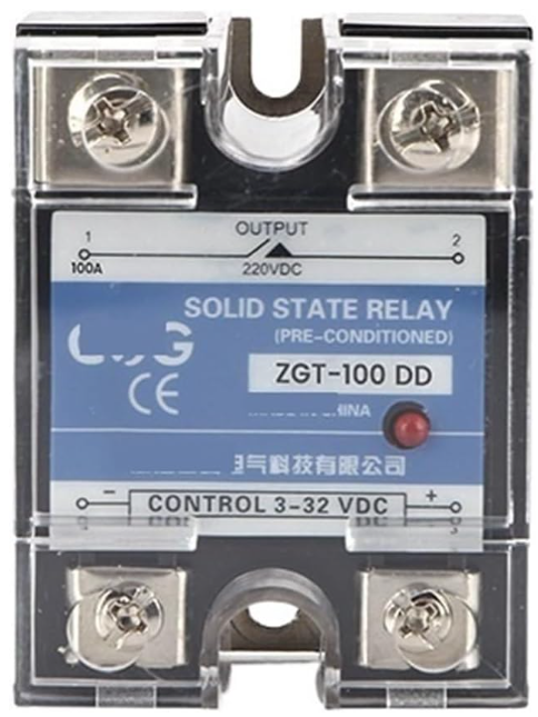
The NURII DD10-120A, DC Control DC SSR Regulator Module 220V (ZGT-100DD) is a single-phase solid state relay (SSR) designed for industrial and scientific applications. Unlike traditional electromechanical relays, this SSR uses semiconductor devices to control electrical loads, offering faster switching speeds, longer operational life, and reduced mechanical wear.
This SSR is ideal for controlling high-power devices such as motors, heaters, and industrial equipment. Its compact design and reliable performance make it a popular choice for automation systems, temperature control, and other industrial processes.
Explore Projects Built with Single Phase Solid State Relay: Industrial & Scientific


Explore Projects Built with Single Phase Solid State Relay: Industrial & Scientific
Common Applications:
- Industrial motor control
- Heating element regulation
- Lighting systems
- Temperature control in ovens and furnaces
- Automation systems in manufacturing
Technical Specifications
Key Technical Details:
| Parameter | Value |
|---|---|
| Manufacturer | NURII |
| Part ID | DD10-120A (ZGT-100DD) |
| Control Voltage (Input) | 3-32V DC |
| Load Voltage (Output) | 24-220V AC |
| Load Current (Output) | 0-120A |
| Switching Type | Zero-crossing |
| Isolation Voltage | ≥2500V AC |
| Operating Temperature | -30°C to +80°C |
| Mounting Type | Panel Mount |
| Dimensions | 58mm x 45mm x 30mm |
| Weight | ~120g |
Pin Configuration and Descriptions:
| Pin Number | Pin Name | Description |
|---|---|---|
| 1 | DC+ (Input) | Positive terminal for the DC control signal (3-32V DC). |
| 2 | DC- (Input) | Negative terminal for the DC control signal (ground). |
| 3 | AC Load (L1) | Connect to one side of the AC load. |
| 4 | AC Load (L2) | Connect to the other side of the AC load. |
Usage Instructions
How to Use the Component in a Circuit:
Control Signal Connection:
- Connect the DC control signal (3-32V DC) to the
DC+andDC-pins. Ensure the polarity is correct. - Use a current-limiting resistor if necessary to protect the control circuit.
- Connect the DC control signal (3-32V DC) to the
Load Connection:
- Connect the AC load (e.g., motor, heater) to the
AC Load (L1)andAC Load (L2)terminals. - Ensure the load voltage and current are within the SSR's rated specifications (24-220V AC, 0-120A).
- Connect the AC load (e.g., motor, heater) to the
Power Supply:
- Ensure the AC power supply matches the load requirements and is properly grounded.
Mounting:
- Securely mount the SSR on a heat sink or panel to ensure proper heat dissipation. Use thermal paste if necessary.
Testing:
- Apply the control signal to the
DC+andDC-terminals. The SSR should switch the AC load on or off based on the control signal.
- Apply the control signal to the
Important Considerations and Best Practices:
- Heat Dissipation: Use a heat sink or cooling fan to prevent overheating during high-current operation.
- Isolation: Ensure proper electrical isolation between the control and load circuits to avoid damage.
- Surge Protection: Use a snubber circuit or varistor to protect the SSR from voltage spikes.
- Wiring: Use appropriately rated wires and connectors for the load current to prevent overheating or fire hazards.
- Testing: Verify the control signal and load connections before powering the circuit.
Example: Controlling an AC Load with Arduino UNO
Below is an example of how to control the SSR using an Arduino UNO to switch an AC load (e.g., a light bulb).
// Define the control pin for the SSR
const int ssrControlPin = 9; // Connect this pin to the DC+ terminal of the SSR

void setup() {
  pinMode(ssrControlPin, OUTPUT); // Set the SSR control pin as an output
}

void loop() {
  digitalWrite(ssrControlPin, HIGH); // Turn the SSR ON (AC load ON)
  delay(5000); // Keep the load ON for 5 seconds

  digitalWrite(ssrControlPin, LOW); // Turn the SSR OFF (AC load OFF)
  delay(5000); // Keep the load OFF for 5 seconds
}
Note: Ensure the Arduino's output voltage (5V) is compatible with the SSR's control voltage range (3-32V DC). If necessary, use a transistor or MOSFET to amplify the control signal.
Troubleshooting and FAQs
Common Issues and Solutions:
SSR Does Not Switch the Load:
- Cause: Incorrect control signal voltage or polarity.
- Solution: Verify the control signal is within the 3-32V DC range and the polarity is correct.
Overheating:
- Cause: Insufficient heat dissipation or excessive load current.
- Solution: Use a heat sink or cooling fan, and ensure the load current does not exceed 120A.
Load Flickering:
- Cause: Unstable control signal or insufficient load current.
- Solution: Ensure the control signal is stable and the load meets the SSR's minimum current requirements.
SSR Fails to Turn Off:
- Cause: Leakage current or incorrect wiring.
- Solution: Check the wiring and ensure the load is properly connected. Use a snubber circuit if necessary.
FAQs:
Q: Can this SSR be used with DC loads?
- A: No, this SSR is designed for AC loads only. For DC loads, use a DC-specific SSR.
Q: Is an external heat sink required?
- A: Yes, a heat sink is recommended for high-current applications to prevent overheating.
Q: Can I control the SSR with a 3.3V microcontroller?
- A: Yes, the SSR supports control voltages as low as 3V DC, making it compatible with 3.3V systems.
Q: What is the maximum switching frequency?
- A: The SSR is suitable for low to moderate switching frequencies, typically up to a few Hz. For high-frequency switching, consult the manufacturer.
This concludes the documentation for the NURII DD10-120A, DC Control DC SSR Regulator Module 220V (ZGT-100DD). For further assistance, refer to the manufacturer's datasheet or contact technical support.