How to Use Piezo sensor: Examples, Pinouts, and Specs
Introduction
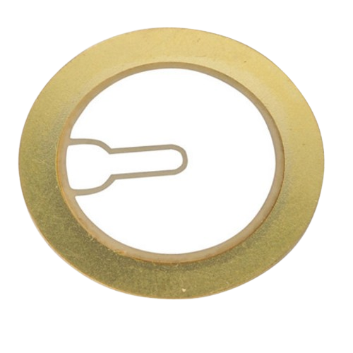
The Piezo Sensor (Manufacturer: Diode House, Part ID: Piezo Disc) is a versatile electronic component that generates an electrical charge when subjected to mechanical stress. This property makes it ideal for applications requiring the detection of pressure, vibration, or acceleration. Piezo sensors are widely used in various fields, including industrial monitoring, musical instruments, medical devices, and consumer electronics.
Explore Projects Built with Piezo sensor
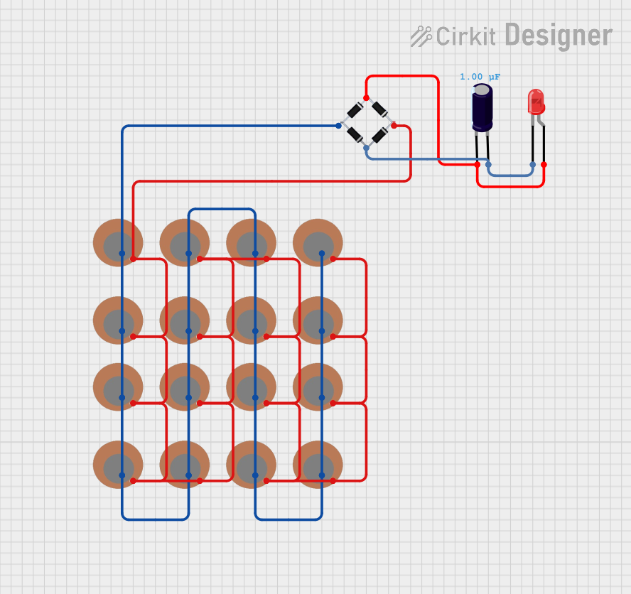
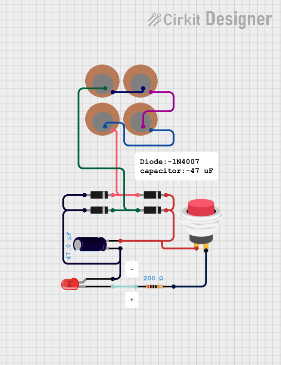
Explore Projects Built with Piezo sensor
Common Applications and Use Cases
- Vibration detection: Used in machinery to monitor vibrations and detect faults.
- Impact sensing: Commonly used in touch-sensitive devices and musical instruments.
- Sound generation: Functions as a buzzer or speaker in alarms and notifications.
- Force measurement: Utilized in load cells and pressure sensors.
- Energy harvesting: Converts mechanical energy into electrical energy for low-power devices.
Technical Specifications
The following table outlines the key technical details of the Piezo Sensor (Piezo Disc):
| Parameter | Value |
|---|---|
| Manufacturer | Diode House |
| Part ID | Piezo Disc |
| Operating Voltage | 0 - 30 V |
| Output Voltage Range | Up to 90 V (peak-to-peak) |
| Operating Frequency | 1 - 5 kHz |
| Sensitivity | ~50 mV/g (varies by model) |
| Diameter | 27 mm |
| Thickness | 0.5 mm |
| Material | Lead zirconate titanate (PZT) |
| Operating Temperature | -20°C to 70°C |
Pin Configuration and Descriptions
The Piezo Sensor typically has two terminals:
| Pin | Description |
|---|---|
| Positive (+) | Connects to the positive input of the circuit. This terminal generates a positive voltage when the sensor is stressed. |
| Negative (-) | Connects to the ground or negative input of the circuit. |
Usage Instructions
How to Use the Piezo Sensor in a Circuit
- Connection: Connect the positive terminal of the Piezo Sensor to the input of your circuit (e.g., an amplifier or microcontroller). The negative terminal should be connected to the ground.
- Signal Conditioning: Since the Piezo Sensor generates a high-impedance signal, use an operational amplifier (op-amp) or a buffer circuit to amplify and condition the signal for further processing.
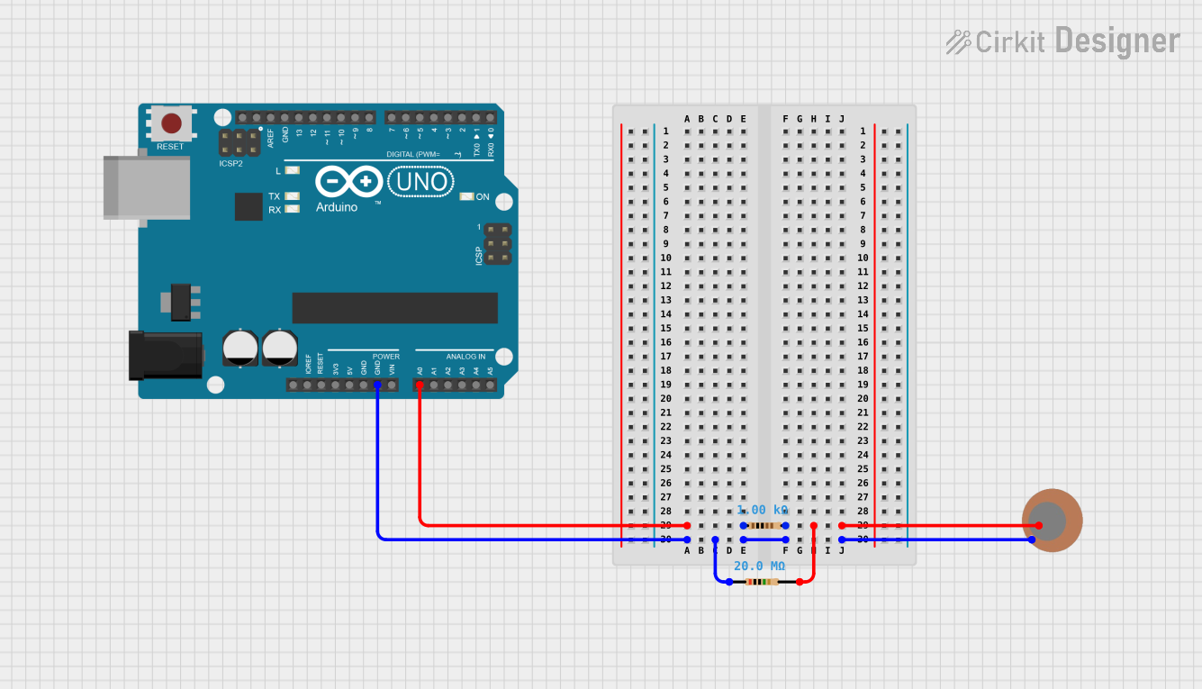
- Microcontroller Interface: If connecting to a microcontroller like an Arduino UNO, use an analog input pin to read the sensor's output voltage. A resistor (e.g., 1 MΩ) may be added in parallel to the sensor to stabilize the signal.
Important Considerations and Best Practices
- High Impedance: The Piezo Sensor has a high output impedance, so ensure that the input impedance of the connected circuit is sufficiently high to avoid signal loss.
- Voltage Spikes: The sensor can generate high voltage spikes. Use a protection circuit (e.g., a Zener diode) to prevent damage to sensitive components.
- Mounting: Secure the sensor properly to ensure accurate detection of mechanical stress. Avoid excessive force that could damage the sensor.
- Environmental Factors: Operate the sensor within its specified temperature range (-20°C to 70°C) to maintain performance and longevity.
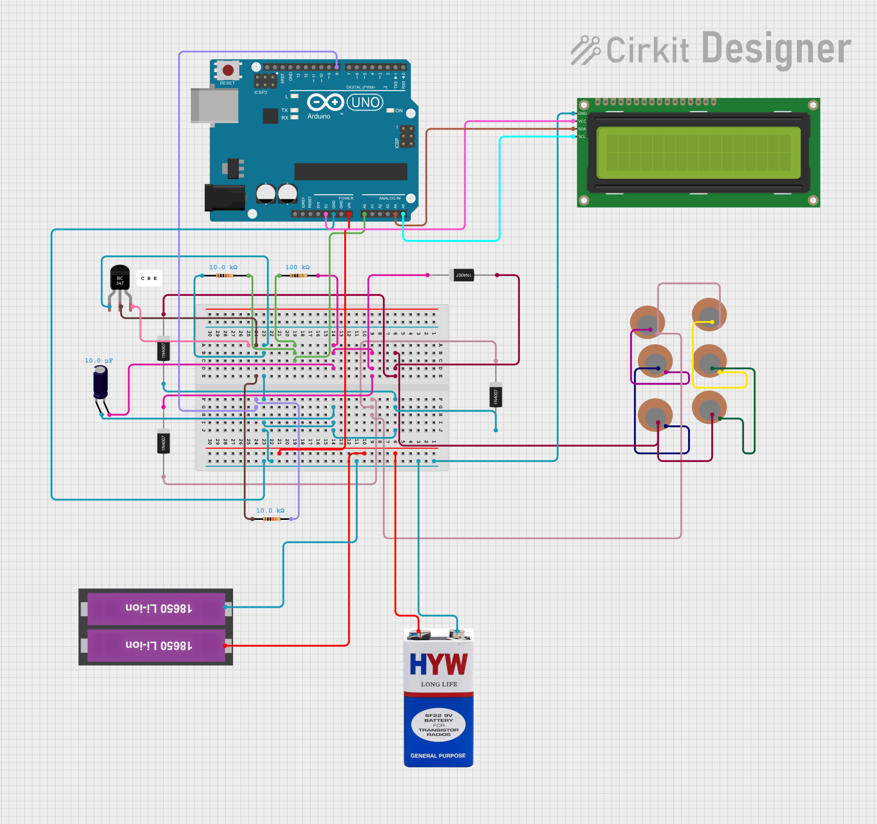
Example: Connecting a Piezo Sensor to an Arduino UNO
Below is an example of how to connect and read data from a Piezo Sensor using an Arduino UNO:
// Piezo Sensor Example with Arduino UNO
// Reads the analog signal from the Piezo Sensor and prints it to the Serial Monitor.

const int piezoPin = A0; // Connect the positive terminal of the Piezo Sensor to A0
                         // and the negative terminal to GND.

void setup() {
  Serial.begin(9600); // Initialize serial communication at 9600 baud
}

void loop() {
  int sensorValue = analogRead(piezoPin); // Read the analog value from the sensor
  Serial.println(sensorValue); // Print the sensor value to the Serial Monitor

  delay(100); // Delay for 100 ms to avoid flooding the Serial Monitor
}
Troubleshooting and FAQs
Common Issues and Solutions
No Output Signal:
- Cause: Loose or incorrect connections.
- Solution: Verify that the positive and negative terminals are connected correctly. Ensure the circuit is powered and the sensor is securely mounted.
Weak Signal:
- Cause: High impedance mismatch or insufficient amplification.
- Solution: Use an op-amp or buffer circuit to amplify the signal. Check the input impedance of the connected circuit.
Erratic Readings:
- Cause: Electrical noise or unstable connections.
- Solution: Add a capacitor (e.g., 0.1 µF) across the sensor terminals to filter noise. Ensure all connections are stable.
Sensor Damage:
- Cause: Excessive mechanical stress or operation outside the specified temperature range.
- Solution: Handle the sensor carefully and operate it within the recommended specifications.
FAQs
Q1: Can the Piezo Sensor be used to generate sound?
A1: Yes, the Piezo Sensor can act as a buzzer or speaker when connected to an AC signal source.
Q2: How do I measure force using the Piezo Sensor?
A2: The output voltage of the sensor is proportional to the applied force. Use a calibrated circuit to convert the voltage into a force measurement.
Q3: Can the Piezo Sensor be used for energy harvesting?
A3: Yes, the Piezo Sensor can generate electrical energy from mechanical vibrations, but the output power is typically low and requires a rectifier and storage circuit.
Q4: What is the lifespan of the Piezo Sensor?
A4: The lifespan depends on the operating conditions, but under normal use, it can last for several years. Avoid excessive stress and extreme temperatures to maximize its longevity.