Cirkit Designer Logo
Cirkit Designer
Your all-in-one circuit design IDE
Home / 
Component Documentation

How to Use MPQ6610: Examples, Pinouts, and Specs

Image of MPQ6610
Cirkit Designer LogoDesign with MPQ6610 in Cirkit Designer

Introduction

The MPQ6610, manufactured by MPS, is a high-side power switch specifically designed for automotive applications. This component is known for its low on-resistance, over-current protection, and thermal shutdown features, ensuring reliable operation even in harsh environments. The MPQ6610 is ideal for applications such as power distribution, load switching, and automotive lighting systems.

Explore Projects Built with MPQ6610

Use Cirkit Designer to design, explore, and prototype these projects online. Some projects support real-time simulation. Click "Open Project" to start designing instantly!
Battery-Powered MP3 Player with Amplified Dual Speakers
Image of bluethooth speaker( 2 speaker): A project utilizing MPQ6610 in a practical application
This circuit is a portable audio playback system powered by two 18650 Li-ion batteries, which are charged and protected by a TP4056 module. The MP3 module provides audio signals to a 5V amplifier board, which then drives two speakers. A push switch is used to control the power to the MP3 module and amplifier.
Cirkit Designer LogoOpen Project in Cirkit Designer
Arduino Pro Mini and HC-05 Bluetooth Controlled Coreless Motor Clock with MPU-6050 Feedback
Image of drone: A project utilizing MPQ6610 in a practical application
This is a motion-controlled device with wireless capabilities, powered by a LiPo battery with voltage regulation. It uses an Arduino Pro Mini to process MPU-6050 sensor data and control coreless motors via MOSFETs, interfacing with an external device through an HC-05 Bluetooth module.
Cirkit Designer LogoOpen Project in Cirkit Designer
Battery-Powered Raspberry Pi Pico GPS Tracker with Sensor Integration
Image of Copy of CanSet v1: A project utilizing MPQ6610 in a practical application
This circuit is a data acquisition and communication system powered by a LiPoly battery and managed by a Raspberry Pi Pico. It includes sensors (BMP280, MPU9250) for environmental data, a GPS module for location tracking, an SD card for data storage, and a WLR089-CanSAT for wireless communication. The TP4056 module handles battery charging, and a toggle switch controls power distribution.
Cirkit Designer LogoOpen Project in Cirkit Designer
A-Star 32U4 Mini Controlled MP3 Player with Loudspeaker
Image of Speaker: A project utilizing MPQ6610 in a practical application
This circuit integrates an A-Star 32U4 Mini microcontroller with an MP3 Decoder Player Module to create a basic MP3 player system. The microcontroller is likely used to control playback functions such as mode selection and track navigation, as indicated by the connections to the Mode, Repeat, Prev/V--, and Next/V++ pins of the MP3 module. The Loudspeaker is connected to the MP3 module to output the audio signal.
Cirkit Designer LogoOpen Project in Cirkit Designer

Explore Projects Built with MPQ6610

Use Cirkit Designer to design, explore, and prototype these projects online. Some projects support real-time simulation. Click "Open Project" to start designing instantly!
Image of bluethooth speaker( 2 speaker): A project utilizing MPQ6610 in a practical application
Battery-Powered MP3 Player with Amplified Dual Speakers
This circuit is a portable audio playback system powered by two 18650 Li-ion batteries, which are charged and protected by a TP4056 module. The MP3 module provides audio signals to a 5V amplifier board, which then drives two speakers. A push switch is used to control the power to the MP3 module and amplifier.
Cirkit Designer LogoOpen Project in Cirkit Designer
Image of drone: A project utilizing MPQ6610 in a practical application
Arduino Pro Mini and HC-05 Bluetooth Controlled Coreless Motor Clock with MPU-6050 Feedback
This is a motion-controlled device with wireless capabilities, powered by a LiPo battery with voltage regulation. It uses an Arduino Pro Mini to process MPU-6050 sensor data and control coreless motors via MOSFETs, interfacing with an external device through an HC-05 Bluetooth module.
Cirkit Designer LogoOpen Project in Cirkit Designer
Image of Copy of CanSet v1: A project utilizing MPQ6610 in a practical application
Battery-Powered Raspberry Pi Pico GPS Tracker with Sensor Integration
This circuit is a data acquisition and communication system powered by a LiPoly battery and managed by a Raspberry Pi Pico. It includes sensors (BMP280, MPU9250) for environmental data, a GPS module for location tracking, an SD card for data storage, and a WLR089-CanSAT for wireless communication. The TP4056 module handles battery charging, and a toggle switch controls power distribution.
Cirkit Designer LogoOpen Project in Cirkit Designer
Image of Speaker: A project utilizing MPQ6610 in a practical application
A-Star 32U4 Mini Controlled MP3 Player with Loudspeaker
This circuit integrates an A-Star 32U4 Mini microcontroller with an MP3 Decoder Player Module to create a basic MP3 player system. The microcontroller is likely used to control playback functions such as mode selection and track navigation, as indicated by the connections to the Mode, Repeat, Prev/V--, and Next/V++ pins of the MP3 module. The Loudspeaker is connected to the MP3 module to output the audio signal.
Cirkit Designer LogoOpen Project in Cirkit Designer

Technical Specifications

Key Technical Details

Parameter Value
Operating Voltage Range 4.5V to 40V
On-Resistance (RDS(on)) 50mΩ (typical)
Maximum Load Current 2A
Over-Current Protection Yes
Thermal Shutdown Yes
Operating Temperature -40°C to +125°C
Package SOIC-8

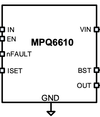
Pin Configuration and Descriptions

Pin Number Pin Name Description
1 IN Input voltage
2 GND Ground
3 EN Enable pin (active high)
4 NC No connection
5 NC No connection
6 NC No connection
7 OUT Output voltage
8 FLT Fault indicator (active low)

Usage Instructions

How to Use the MPQ6610 in a Circuit

  1. Power Supply Connection: Connect the input voltage (4.5V to 40V) to the IN pin and the ground to the GND pin.
  2. Load Connection: Connect the load between the OUT pin and ground.
  3. Enable Pin: To turn on the switch, apply a high signal (typically 3.3V or 5V) to the EN pin. To turn off the switch, apply a low signal (0V) to the EN pin.
  4. Fault Indicator: The FLT pin can be connected to a microcontroller or an LED to indicate fault conditions. The pin is active low, meaning it will go low when a fault is detected.

Important Considerations and Best Practices

  • Thermal Management: Ensure proper heat dissipation by using adequate PCB copper area around the device.
  • Over-Current Protection: The MPQ6610 includes over-current protection. Ensure that the load current does not exceed the maximum rating of 2A.
  • Decoupling Capacitors: Place a decoupling capacitor (e.g., 0.1µF) close to the IN pin to filter out noise and ensure stable operation.
  • Fault Handling: Monitor the FLT pin to detect and handle fault conditions such as over-current or thermal shutdown.

Example Circuit with Arduino UNO

// Example code to control MPQ6610 with Arduino UNO

const int enablePin = 7; // Pin connected to EN pin of MPQ6610
const int faultPin = 8;  // Pin connected to FLT pin of MPQ6610

void setup() {
  pinMode(enablePin, OUTPUT); // Set enable pin as output
  pinMode(faultPin, INPUT);   // Set fault pin as input
  digitalWrite(enablePin, LOW); // Initially turn off the switch
  Serial.begin(9600); // Initialize serial communication
}

void loop() {
  // Turn on the switch
  digitalWrite(enablePin, HIGH);
  delay(1000); // Keep the switch on for 1 second

  // Check for fault condition
  if (digitalRead(faultPin) == LOW) {
    Serial.println("Fault detected!");
  } else {
    Serial.println("No fault.");
  }

  // Turn off the switch
  digitalWrite(enablePin, LOW);
  delay(1000); // Keep the switch off for 1 second
}

Troubleshooting and FAQs

Common Issues and Solutions

  1. Switch Not Turning On:

    • Check Power Supply: Ensure the input voltage is within the specified range (4.5V to 40V).
    • Enable Pin: Verify that the EN pin is receiving a high signal (3.3V or 5V).
  2. Fault Indicator Active:

    • Over-Current Condition: Check if the load current exceeds 2A. Reduce the load if necessary.
    • Thermal Shutdown: Ensure proper heat dissipation. Check for any obstructions to airflow or inadequate PCB copper area.
  3. Noise and Unstable Operation:

    • Decoupling Capacitors: Ensure a decoupling capacitor is placed close to the IN pin.
    • PCB Layout: Verify that the PCB layout follows best practices for power and ground connections.

FAQs

Q1: Can the MPQ6610 be used with a 12V automotive battery? A1: Yes, the MPQ6610 can operate with input voltages ranging from 4.5V to 40V, making it suitable for use with a 12V automotive battery.

Q2: How do I know if the MPQ6610 has entered thermal shutdown? A2: The FLT pin will go low if a fault condition, such as thermal shutdown, is detected. Monitor the FLT pin to identify such conditions.

Q3: Can I use the MPQ6610 to switch inductive loads? A3: Yes, but it is recommended to use a flyback diode across the inductive load to protect the switch from voltage spikes.

By following this documentation, users can effectively integrate the MPQ6610 high-side power switch into their automotive and other power distribution applications, ensuring reliable and efficient operation.