How to Use 850nm IR LED Module: Examples, Pinouts, and Specs
Introduction
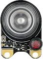
The 850nm IR LED Module (Manufacturer Part ID: 104735) by Shenzhen Xuan Yao Electronics CO Limited is a light-emitting diode designed to emit infrared light at a wavelength of 850 nanometers. This module is widely used in applications requiring invisible light, such as remote controls, optical communication systems, night vision devices, and proximity sensors. Its compact design and ease of integration make it a popular choice for both hobbyists and professionals.
Explore Projects Built with 850nm IR LED Module
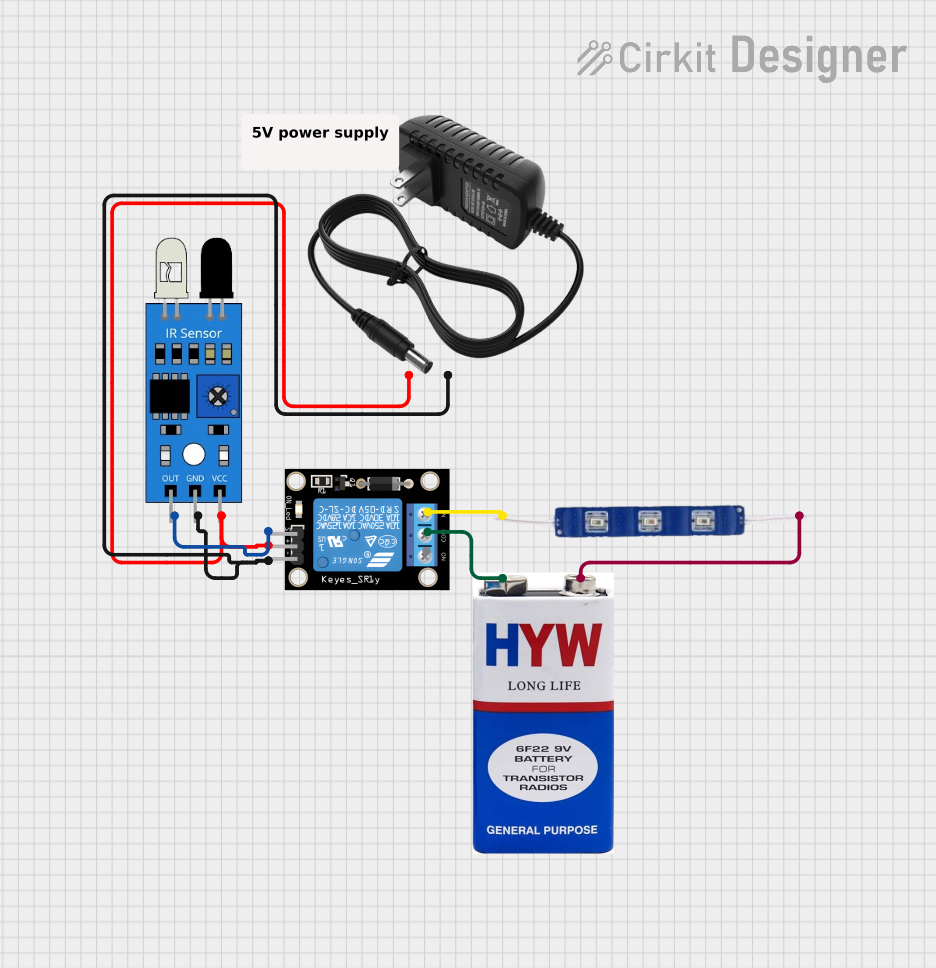
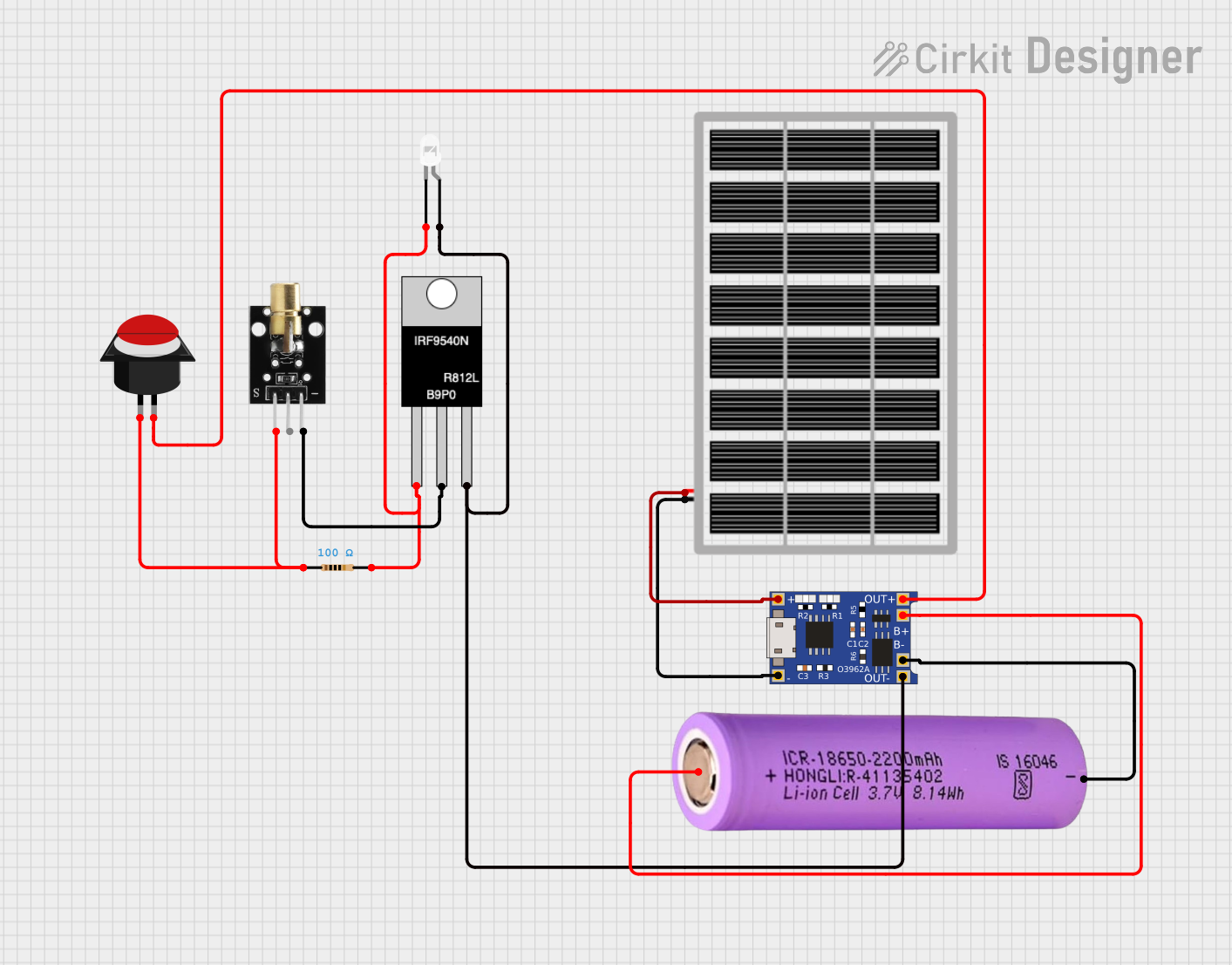
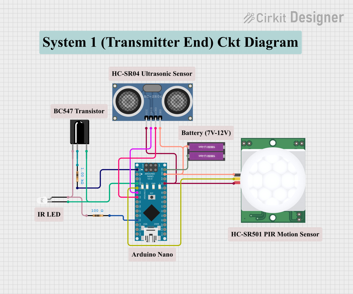

Explore Projects Built with 850nm IR LED Module
Common Applications
- Remote Controls: Used in TVs, air conditioners, and other consumer electronics.
- Night Vision Systems: Provides illumination for cameras and goggles in low-light conditions.
- Optical Communication: Enables data transmission using infrared light.
- Proximity Sensors: Detects objects or motion in automation and robotics.
Technical Specifications
Key Technical Details
| Parameter | Value |
|---|---|
| Wavelength | 850 nm |
| Forward Voltage (Vf) | 1.2V to 1.6V |
| Forward Current (If) | 20mA (typical), 50mA (max) |
| Power Dissipation | 100mW (max) |
| Viewing Angle | 20° to 30° |
| Operating Temperature | -25°C to +85°C |
| Storage Temperature | -40°C to +100°C |
Pin Configuration and Descriptions
The 850nm IR LED Module typically has two pins: Anode and Cathode.
| Pin Name | Description | Connection Notes |
|---|---|---|
| Anode | Positive terminal of the LED | Connect to the positive voltage supply. |
| Cathode | Negative terminal of the LED | Connect to ground or the negative terminal. |
Usage Instructions
How to Use the Component in a Circuit
Power Supply: Ensure the module is powered with a voltage between 1.2V and 1.6V. Use a current-limiting resistor to prevent overcurrent damage.
- Calculate the resistor value using Ohm's Law:
( R = \frac{V_{supply} - V_f}{I_f} )
For example, with a 5V supply and a forward voltage of 1.4V at 20mA:
( R = \frac{5V - 1.4V}{0.02A} = 180 , \Omega ).
- Calculate the resistor value using Ohm's Law:
Circuit Connection:
- Connect the Anode to the positive terminal of the power supply through the current-limiting resistor.
- Connect the Cathode to the ground.
Testing: Use a camera (e.g., a smartphone camera) to verify the IR LED is emitting light, as infrared light is not visible to the human eye.
Important Considerations and Best Practices
- Current Limiting: Always use a resistor to limit the current through the LED to avoid damage.
- Heat Management: Ensure proper ventilation or heat dissipation if the module is used continuously at high currents.
- Polarity: Double-check the polarity before powering the module. Reversing the connections can damage the LED.
- Distance and Angle: For optimal performance, consider the viewing angle and distance to the target.
Example: Connecting to an Arduino UNO
The 850nm IR LED Module can be easily interfaced with an Arduino UNO for applications like remote control or object detection.
Circuit Diagram
- Connect the Anode of the IR LED to a digital pin (e.g., Pin 9) on the Arduino through a 220Ω resistor.
- Connect the Cathode to the Arduino's GND.
Arduino Code Example
// Example code to blink the 850nm IR LED using Arduino UNO
// The IR LED is connected to Pin 9 through a 220Ω resistor

const int irLedPin = 9; // Define the pin connected to the IR LED

void setup() {
  pinMode(irLedPin, OUTPUT); // Set the IR LED pin as an output
}

void loop() {
  digitalWrite(irLedPin, HIGH); // Turn the IR LED on
  delay(1000);                  // Wait for 1 second
  digitalWrite(irLedPin, LOW);  // Turn the IR LED off
  delay(1000);                  // Wait for 1 second
}
Troubleshooting and FAQs
Common Issues and Solutions
IR LED Not Emitting Light:
- Cause: Incorrect polarity or insufficient voltage.
- Solution: Verify the connections and ensure the power supply matches the required forward voltage.
Overheating:
- Cause: Excessive current through the LED.
- Solution: Use an appropriate current-limiting resistor and ensure proper ventilation.
No Response in Application:
- Cause: Misalignment or obstruction in the IR path.
- Solution: Check the alignment and ensure there are no obstacles blocking the IR signal.
IR LED Works Intermittently:
- Cause: Loose connections or fluctuating power supply.
- Solution: Secure all connections and use a stable power source.
FAQs
Q1: How can I test if the IR LED is working?
A1: Use a smartphone or digital camera to view the LED while it is powered. The camera can detect infrared light, which will appear as a faint glow.
Q2: Can I use the IR LED without a resistor?
A2: No, a resistor is necessary to limit the current and prevent damage to the LED.
Q3: What is the maximum range of the 850nm IR LED?
A3: The range depends on the power supply, viewing angle, and environmental conditions. Typically, it can range from a few meters to over 10 meters in optimal conditions.
Q4: Is the 850nm wavelength safe for human eyes?
A4: Yes, 850nm infrared light is generally safe, but prolonged exposure at high intensities should be avoided.
This concludes the documentation for the 850nm IR LED Module. For further assistance, refer to the manufacturer's datasheet or contact technical support.