How to Use HLK: Examples, Pinouts, and Specs
Introduction
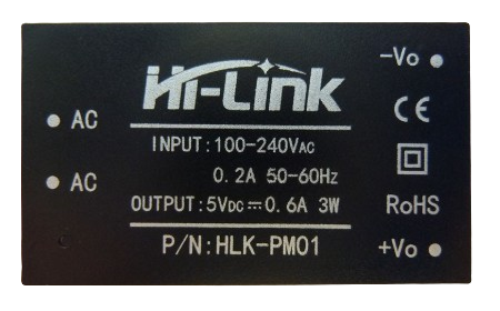
The HLK-PM01 is a compact, high-efficiency AC-DC power module manufactured by HI LINK. This module is designed to convert AC mains voltage to a stable DC output, making it an ideal choice for powering various electronic devices. Its small size and high efficiency make it suitable for applications where space and power efficiency are critical.
Explore Projects Built with HLK


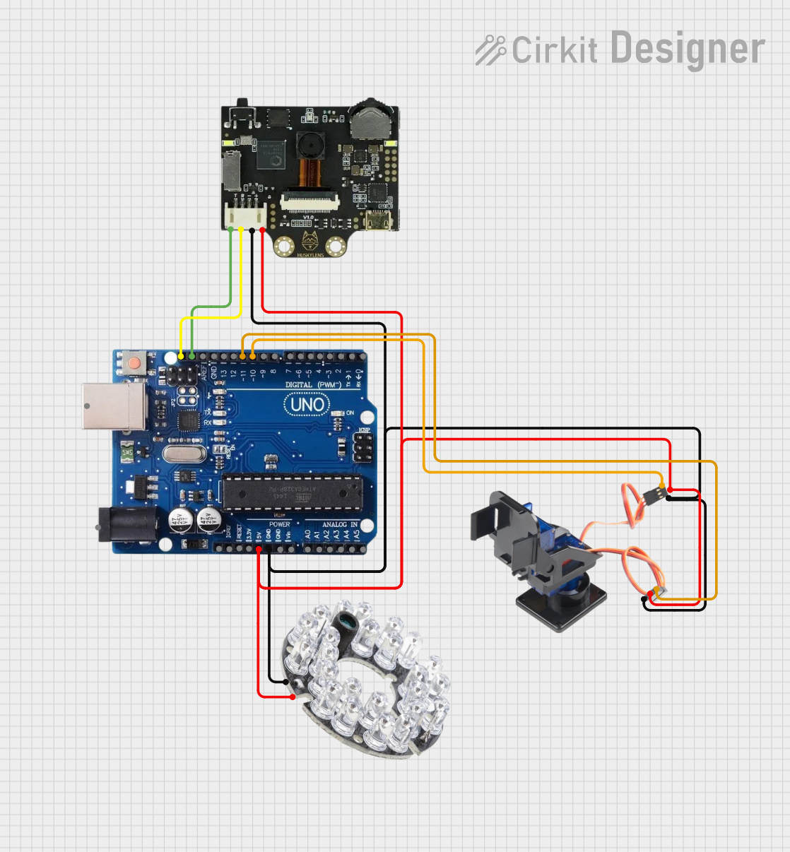

Explore Projects Built with HLK
Common Applications and Use Cases
- Home Automation: Powering sensors, relays, and microcontrollers in smart home systems.
- IoT Devices: Providing a stable power supply for Internet of Things (IoT) devices.
- Embedded Systems: Supplying power to embedded systems and development boards.
- Consumer Electronics: Used in chargers, adapters, and other consumer electronic devices.
Technical Specifications
Key Technical Details
| Parameter | Value |
|---|---|
| Input Voltage | 90-264V AC |
| Output Voltage | 5V DC |
| Output Current | 600mA |
| Output Power | 3W |
| Efficiency | ≥70% |
| Ripple & Noise | ≤50mV |
| Operating Temp. | -25°C to +60°C |
| Storage Temp. | -40°C to +80°C |
| Dimensions | 35mm x 18mm x 15mm |
| Weight | 12g |
Pin Configuration and Descriptions
| Pin Number | Pin Name | Description |
|---|---|---|
| 1 | AC(L) | Live AC input |
| 2 | AC(N) | Neutral AC input |
| 3 | +Vout | Positive DC output (5V) |
| 4 | -Vout | Negative DC output (Ground) |
Usage Instructions
How to Use the Component in a Circuit
- Safety First: Ensure that the power is turned off before making any connections.
- Connect AC Input: Connect the AC(L) pin to the live wire and the AC(N) pin to the neutral wire of the AC mains.
- Connect DC Output: Connect the +Vout pin to the positive terminal of your load and the -Vout pin to the ground terminal.
- Power On: Once all connections are secure, turn on the AC mains power.
Important Considerations and Best Practices
- Isolation: Ensure proper isolation between the AC and DC sides to prevent electrical hazards.
- Heat Dissipation: Although the module is efficient, ensure adequate ventilation to avoid overheating.
- Load Requirements: Do not exceed the maximum output current of 600mA to prevent damage to the module.
- Surge Protection: Consider adding surge protection components to safeguard against voltage spikes.
Troubleshooting and FAQs
Common Issues and Solutions
No Output Voltage:
- Check Connections: Ensure all connections are secure and correct.
- Verify Input Voltage: Ensure the AC mains voltage is within the specified range (90-264V AC).
- Inspect Module: Check for any visible damage to the module.
Overheating:
- Ventilation: Ensure the module has adequate ventilation.
- Load Check: Verify that the load does not exceed the maximum output current of 600mA.
Output Voltage Fluctuations:
- Stable Input: Ensure the AC input voltage is stable and within the specified range.
- Load Stability: Check if the load is stable and not causing sudden current spikes.
FAQs
Q1: Can I use the HLK-PM01 to power my Arduino UNO?
- A1: Yes, the HLK-PM01 can be used to power an Arduino UNO. Connect the +Vout to the 5V pin and the -Vout to the GND pin of the Arduino.
Q2: Is the HLK-PM01 suitable for outdoor use?
- A2: The HLK-PM01 is not designed for outdoor use. It should be used in a dry, indoor environment.
Q3: What should I do if the module stops working?
- A3: First, check all connections and ensure the input voltage is within the specified range. If the problem persists, the module may be damaged and require replacement.
Example Code for Arduino UNO
Below is an example code to power an Arduino UNO using the HLK-PM01 module:
// Example code to blink an LED on Arduino UNO powered by HLK-PM01

const int ledPin = 13; // Pin number for the onboard LED

void setup() {
  pinMode(ledPin, OUTPUT); // Set the LED pin as an output
}

void loop() {
  digitalWrite(ledPin, HIGH); // Turn the LED on
  delay(1000); // Wait for 1 second
  digitalWrite(ledPin, LOW); // Turn the LED off
  delay(1000); // Wait for 1 second
}
This code will blink the onboard LED of the Arduino UNO, demonstrating a simple use case of the HLK-PM01 module as a power supply.
This documentation provides a comprehensive overview of the HLK-PM01 AC-DC power module, including its technical specifications, usage instructions, and troubleshooting tips. Whether you are a beginner or an experienced user, this guide will help you effectively utilize the HLK-PM01 in your projects.