Cirkit Designer
Your all-in-one circuit design IDE
Home /
Component Documentation
How to Use Seeed Studio XIAO ESP32S3(Sense): Examples, Pinouts, and Specs
Introduction
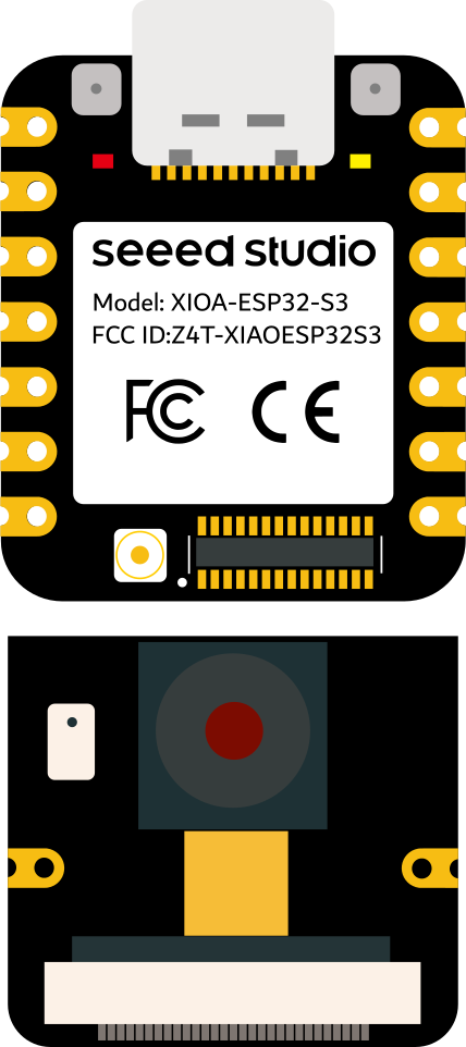
The Seeed Studio XIAO ESP32S3(Sense) is a compact microcontroller board powered by the ESP32-S3 chip. It is specifically designed for IoT (Internet of Things) applications, offering built-in Wi-Fi and Bluetooth connectivity. This board also features integrated sensors, making it ideal for environmental monitoring, smart devices, and interactive projects. Its small form factor and powerful capabilities make it a versatile choice for both hobbyists and professionals.
Explore Projects Built with Seeed Studio XIAO ESP32S3(Sense)
ESP32-Based Multi-Sensor Health Monitoring System with Bluetooth Connectivity

This circuit features an ESP32-WROOM-32UE microcontroller as the central processing unit, interfacing with a variety of sensors and modules. It includes a MAX30100 pulse oximeter and heart-rate sensor, an MLX90614 infrared thermometer, an HC-05 Bluetooth module for wireless communication, and a Neo 6M GPS module for location tracking. All components are powered by a common voltage supply and are connected to specific GPIO pins on the ESP32 for data exchange, with the sensors using I2C communication and the modules using UART.
Xiao ESP32 C3 Based Temperature and Humidity Monitoring System
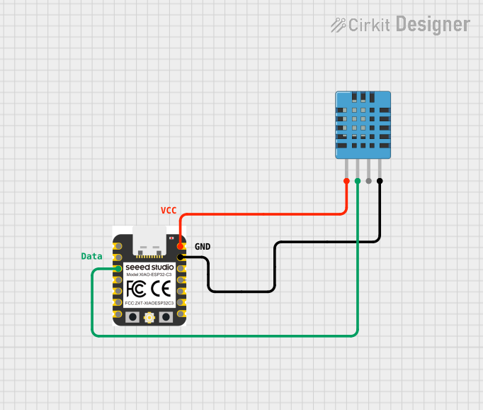
This circuit features a Xiao ESP32 C3 microcontroller connected to a DHT11 Humidity and Temperature Sensor. The ESP32 C3 provides power to the DHT11 sensor through its VUSB pin and receives data from the sensor's DATA pin via the ESP32's D2 pin. The circuit is designed to measure environmental temperature and humidity, with the microcontroller processing and potentially communicating the sensor data.
ESP32C3 and LoRa-Enabled Environmental Sensing Node

This circuit features an ESP32C3 Supermini microcontroller connected to a LORA_RA02 module and a DHT11 temperature and humidity sensor. The ESP32C3 handles communication with the LORA module via SPI (using GPIO05, GPIO06, GPIO10, and GPIO04 for MISO, MOSI, NSS, and SCK respectively) and GPIO01 and GPIO02 for additional control signals. The DHT11 sensor is interfaced through GPIO03 for data reading, and all components share a common power supply through the 3.3V and GND pins.
ESP32-Based Smart Weather Station with Wi-Fi Connectivity

This circuit features an ESP32 microcontroller interfacing with various sensors and modules, including a DHT22 temperature and humidity sensor, an ESP32 CAM for image capture, an I2C LCD screen for display, a load cell with an HX711 interface for weight measurement, and a buzzer for audio alerts. The ESP32 handles data acquisition, processing, and communication with these peripherals to create a multi-functional monitoring and alert system.
Explore Projects Built with Seeed Studio XIAO ESP32S3(Sense)
ESP32-Based Multi-Sensor Health Monitoring System with Bluetooth Connectivity
This circuit features an ESP32-WROOM-32UE microcontroller as the central processing unit, interfacing with a variety of sensors and modules. It includes a MAX30100 pulse oximeter and heart-rate sensor, an MLX90614 infrared thermometer, an HC-05 Bluetooth module for wireless communication, and a Neo 6M GPS module for location tracking. All components are powered by a common voltage supply and are connected to specific GPIO pins on the ESP32 for data exchange, with the sensors using I2C communication and the modules using UART.
Xiao ESP32 C3 Based Temperature and Humidity Monitoring System
This circuit features a Xiao ESP32 C3 microcontroller connected to a DHT11 Humidity and Temperature Sensor. The ESP32 C3 provides power to the DHT11 sensor through its VUSB pin and receives data from the sensor's DATA pin via the ESP32's D2 pin. The circuit is designed to measure environmental temperature and humidity, with the microcontroller processing and potentially communicating the sensor data.
ESP32C3 and LoRa-Enabled Environmental Sensing Node
This circuit features an ESP32C3 Supermini microcontroller connected to a LORA_RA02 module and a DHT11 temperature and humidity sensor. The ESP32C3 handles communication with the LORA module via SPI (using GPIO05, GPIO06, GPIO10, and GPIO04 for MISO, MOSI, NSS, and SCK respectively) and GPIO01 and GPIO02 for additional control signals. The DHT11 sensor is interfaced through GPIO03 for data reading, and all components share a common power supply through the 3.3V and GND pins.
ESP32-Based Smart Weather Station with Wi-Fi Connectivity
This circuit features an ESP32 microcontroller interfacing with various sensors and modules, including a DHT22 temperature and humidity sensor, an ESP32 CAM for image capture, an I2C LCD screen for display, a load cell with an HX711 interface for weight measurement, and a buzzer for audio alerts. The ESP32 handles data acquisition, processing, and communication with these peripherals to create a multi-functional monitoring and alert system.
Common Applications
- IoT devices and smart home automation
- Environmental monitoring (e.g., temperature, humidity, air quality)
- Wearable devices
- Robotics and interactive projects
- Prototyping AI and machine learning applications
Technical Specifications
Key Technical Details
| Specification | Value |
|---|---|
| Microcontroller | ESP32-S3 (Xtensa® 32-bit LX7 dual-core) |
| Clock Speed | Up to 240 MHz |
| Flash Memory | 8 MB |
| RAM | 512 KB SRAM + 2 MB PSRAM |
| Connectivity | Wi-Fi 802.11 b/g/n, Bluetooth 5.0 |
| Sensors | IMU (6-axis), Microphone |
| Operating Voltage | 3.3V |
| Input Voltage Range | 5V (via USB-C) |
| GPIO Pins | 11 (including ADC, I2C, SPI, UART, PWM) |
| Dimensions | 21 x 17.5 mm |
Pin Configuration and Descriptions
| Pin Name | Type | Description |
|---|---|---|
| 3V3 | Power | 3.3V output for powering external components |
| GND | Ground | Ground connection |
| D0 | GPIO | General-purpose I/O, supports ADC and PWM |
| D1 | GPIO | General-purpose I/O, supports ADC and PWM |
| D2 | GPIO | General-purpose I/O, supports ADC and PWM |
| D3 | GPIO | General-purpose I/O, supports ADC and PWM |
| D4 | GPIO | General-purpose I/O, supports ADC and PWM |
| RX | UART RX | UART receive pin |
| TX | UART TX | UART transmit pin |
| SCL | I2C Clock | I2C clock line |
| SDA | I2C Data | I2C data line |
Usage Instructions
How to Use the Component in a Circuit
- Powering the Board: Connect the XIAO ESP32S3(Sense) to a 5V power source via the USB-C port. The onboard voltage regulator will step down the voltage to 3.3V.
- Connecting Sensors and Peripherals: Use the GPIO pins to connect external sensors, actuators, or other peripherals. Ensure the voltage levels are compatible with the 3.3V logic of the board.
- Programming the Board: The board can be programmed using the Arduino IDE or other ESP32-compatible development environments. Install the necessary board definitions and libraries before uploading code.
Important Considerations and Best Practices
- Voltage Levels: Ensure all connected components operate at 3.3V logic levels to avoid damaging the board.
- Heat Management: While the board is efficient, prolonged high-performance tasks may generate heat. Ensure proper ventilation if used in enclosed spaces.
- Wi-Fi and Bluetooth Interference: Avoid placing the board near sources of electromagnetic interference to maintain reliable wireless communication.
Example Code for Arduino UNO Integration
Below is an example of how to use the XIAO ESP32S3(Sense) to read data from its onboard IMU sensor and send it to the serial monitor.
#include <Wire.h>
#include <Adafruit_Sensor.h>
#include <Adafruit_LSM6DS33.h>

// Create an instance of the LSM6DS33 sensor
Adafruit_LSM6DS33 lsm6ds;

void setup() {
  Serial.begin(115200); // Initialize serial communication at 115200 baud
  while (!Serial) {
    delay(10); // Wait for the serial connection to be established
  }

  // Initialize the I2C communication
  if (!lsm6ds.begin_I2C()) {
    Serial.println("Failed to initialize LSM6DS33 sensor!");
    while (1) {
      delay(10); // Stay in a loop if initialization fails
    }
  }
  Serial.println("LSM6DS33 sensor initialized successfully!");
}

void loop() {
  sensors_event_t accel, gyro, temp;

  // Get sensor data
  lsm6ds.getEvent(&accel, &gyro, &temp);

  // Print accelerometer data
  Serial.print("Accel X: "); Serial.print(accel.acceleration.x); Serial.print(" m/s^2, ");
  Serial.print("Y: "); Serial.print(accel.acceleration.y); Serial.print(" m/s^2, ");
  Serial.print("Z: "); Serial.print(accel.acceleration.z); Serial.println(" m/s^2");

  // Print gyroscope data
  Serial.print("Gyro X: "); Serial.print(gyro.gyro.x); Serial.print(" rad/s, ");
  Serial.print("Y: "); Serial.print(gyro.gyro.y); Serial.print(" rad/s, ");
  Serial.print("Z: "); Serial.print(gyro.gyro.z); Serial.println(" rad/s");

  // Print temperature data
  Serial.print("Temperature: "); Serial.print(temp.temperature); Serial.println(" °C");

  delay(1000); // Wait 1 second before the next reading
}
Troubleshooting and FAQs
Common Issues
Board Not Detected by Computer:
- Ensure the USB-C cable is a data cable, not just a charging cable.
- Check if the correct drivers for the ESP32-S3 are installed on your computer.
Code Upload Fails:
- Verify that the correct board and port are selected in the Arduino IDE.
- Press the reset button on the board before uploading the code.
Wi-Fi or Bluetooth Not Working:
- Ensure the board is within range of the Wi-Fi network or Bluetooth device.
- Check for interference from other devices operating on the same frequency.
Solutions and Tips
- Resetting the Board: If the board becomes unresponsive, press the reset button to restart it.
- Debugging: Use the serial monitor to print debug messages and identify issues in your code.
- Firmware Updates: Keep the ESP32-S3 firmware up to date to ensure compatibility with the latest libraries and features.