Cirkit Designer Logo
Cirkit Designer
Your all-in-one circuit design IDE
Home / 
Component Documentation

How to Use esp32 wroom 32e: Examples, Pinouts, and Specs

Image of esp32 wroom 32e
Cirkit Designer LogoDesign with esp32 wroom 32e in Cirkit Designer

Introduction

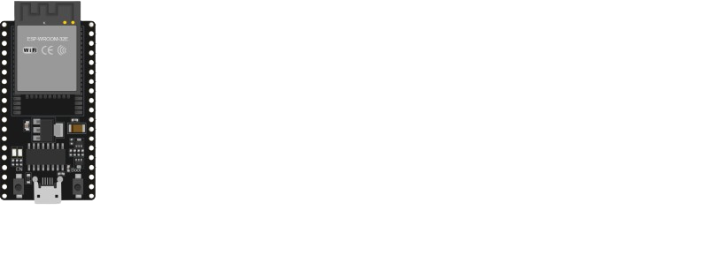
The ESP32-WROOM-32E, manufactured by Espressif Systems (Part ID: DOS), is a powerful and versatile microcontroller module designed for Internet of Things (IoT) applications. It features integrated Wi-Fi and Bluetooth capabilities, dual-core processing, and a wide range of GPIO pins, making it suitable for a variety of projects, from home automation to industrial control systems.

Explore Projects Built with esp32 wroom 32e

Use Cirkit Designer to design, explore, and prototype these projects online. Some projects support real-time simulation. Click "Open Project" to start designing instantly!
ESP32-Based GPS Tracker with SD Card Logging and Barometric Sensor
Image of gps projekt circuit: A project utilizing esp32 wroom 32e in a practical application
This circuit features an ESP32 Wroom Dev Kit as the main microcontroller, interfaced with an MPL3115A2 sensor for pressure and temperature readings, and a Neo 6M GPS module for location tracking. The ESP32 is also connected to an SD card reader for data logging purposes. A voltage regulator is used to step down the USB power supply to 3.3V, which powers the ESP32, the sensor, and the SD card reader.
Cirkit Designer LogoOpen Project in Cirkit Designer
ESP32-Based Infrared Proximity Sensing System
Image of ir sensor: A project utilizing esp32 wroom 32e in a practical application
This circuit features an ESP32 Wroom microcontroller connected to an Infrared Proximity Sensor. The ESP32's GPIO33 is interfaced with the sensor's output, allowing the microcontroller to read proximity data. The sensor is powered by the ESP32's 5V output, and both devices share a common ground.
Cirkit Designer LogoOpen Project in Cirkit Designer
ESP32-Based Multi-Sensor Health Monitoring System with Bluetooth Connectivity
Image of circuit diagram: A project utilizing esp32 wroom 32e in a practical application
This circuit features an ESP32-WROOM-32UE microcontroller as the central processing unit, interfacing with a variety of sensors and modules. It includes a MAX30100 pulse oximeter and heart-rate sensor, an MLX90614 infrared thermometer, an HC-05 Bluetooth module for wireless communication, and a Neo 6M GPS module for location tracking. All components are powered by a common voltage supply and are connected to specific GPIO pins on the ESP32 for data exchange, with the sensors using I2C communication and the modules using UART.
Cirkit Designer LogoOpen Project in Cirkit Designer
ESP32-Based Vibration Motor Controller with I2C IO Expansion
Image of VIBRATYION: A project utilizing esp32 wroom 32e in a practical application
This circuit features an ESP32 Wroom Dev Kit microcontroller interfaced with an MCP23017 I/O expansion board via I2C communication, utilizing GPIO 21 and GPIO 22 for SDA and SCL lines, respectively. A vibration motor is controlled by an NPN transistor acting as a switch, with a diode for back EMF protection and a resistor to limit base current. The ESP32 can control the motor by sending signals to the MCP23017, which then interfaces with the transistor to turn the motor on or off.
Cirkit Designer LogoOpen Project in Cirkit Designer

Explore Projects Built with esp32 wroom 32e

Use Cirkit Designer to design, explore, and prototype these projects online. Some projects support real-time simulation. Click "Open Project" to start designing instantly!
Image of gps projekt circuit: A project utilizing esp32 wroom 32e in a practical application
ESP32-Based GPS Tracker with SD Card Logging and Barometric Sensor
This circuit features an ESP32 Wroom Dev Kit as the main microcontroller, interfaced with an MPL3115A2 sensor for pressure and temperature readings, and a Neo 6M GPS module for location tracking. The ESP32 is also connected to an SD card reader for data logging purposes. A voltage regulator is used to step down the USB power supply to 3.3V, which powers the ESP32, the sensor, and the SD card reader.
Cirkit Designer LogoOpen Project in Cirkit Designer
Image of ir sensor: A project utilizing esp32 wroom 32e in a practical application
ESP32-Based Infrared Proximity Sensing System
This circuit features an ESP32 Wroom microcontroller connected to an Infrared Proximity Sensor. The ESP32's GPIO33 is interfaced with the sensor's output, allowing the microcontroller to read proximity data. The sensor is powered by the ESP32's 5V output, and both devices share a common ground.
Cirkit Designer LogoOpen Project in Cirkit Designer
Image of circuit diagram: A project utilizing esp32 wroom 32e in a practical application
ESP32-Based Multi-Sensor Health Monitoring System with Bluetooth Connectivity
This circuit features an ESP32-WROOM-32UE microcontroller as the central processing unit, interfacing with a variety of sensors and modules. It includes a MAX30100 pulse oximeter and heart-rate sensor, an MLX90614 infrared thermometer, an HC-05 Bluetooth module for wireless communication, and a Neo 6M GPS module for location tracking. All components are powered by a common voltage supply and are connected to specific GPIO pins on the ESP32 for data exchange, with the sensors using I2C communication and the modules using UART.
Cirkit Designer LogoOpen Project in Cirkit Designer
Image of VIBRATYION: A project utilizing esp32 wroom 32e in a practical application
ESP32-Based Vibration Motor Controller with I2C IO Expansion
This circuit features an ESP32 Wroom Dev Kit microcontroller interfaced with an MCP23017 I/O expansion board via I2C communication, utilizing GPIO 21 and GPIO 22 for SDA and SCL lines, respectively. A vibration motor is controlled by an NPN transistor acting as a switch, with a diode for back EMF protection and a resistor to limit base current. The ESP32 can control the motor by sending signals to the MCP23017, which then interfaces with the transistor to turn the motor on or off.
Cirkit Designer LogoOpen Project in Cirkit Designer

Common Applications and Use Cases

  • IoT devices and smart home systems
  • Wireless sensor networks
  • Wearable electronics
  • Industrial automation and control
  • Robotics and drones
  • Prototyping and development of connected devices

Technical Specifications

Key Technical Details

  • Processor: Dual-core Xtensa® 32-bit LX6 microprocessor
  • Clock Speed: Up to 240 MHz
  • Flash Memory: 4 MB (external SPI flash)
  • RAM: 520 KB SRAM
  • Wireless Connectivity:
    • Wi-Fi: 802.11 b/g/n (2.4 GHz)
    • Bluetooth: v4.2 BR/EDR and BLE
  • Operating Voltage: 3.0V to 3.6V
  • GPIO Pins: 34 (multipurpose, including ADC, DAC, PWM, I2C, SPI, UART)
  • Power Consumption:
    • Active mode: ~240 mA
    • Deep sleep mode: ~10 µA
  • Operating Temperature: -40°C to 85°C
  • Dimensions: 18 mm x 25.5 mm x 3.1 mm

Pin Configuration and Descriptions

The ESP32-WROOM-32E has 38 pins. Below is a summary of the key pins and their functions:

Pin Number Pin Name Function
1 EN Enable pin. Pull high to enable the module, low to disable.
2 IO0 GPIO0. Can be used for general I/O or boot mode selection.
3 IO2 GPIO2. General-purpose I/O.
4 IO4 GPIO4. General-purpose I/O.
5 IO5 GPIO5. General-purpose I/O.
6 IO12 GPIO12. Can be used as ADC, touch input, or general-purpose I/O.
7 IO13 GPIO13. Can be used as ADC, touch input, or general-purpose I/O.
8 IO14 GPIO14. Can be used as ADC, touch input, or general-purpose I/O.
9 IO15 GPIO15. Can be used as ADC, touch input, or general-purpose I/O.
10 IO16 GPIO16. General-purpose I/O.
11 IO17 GPIO17. General-purpose I/O.
12 IO18 GPIO18. SPI clock or general-purpose I/O.
13 IO19 GPIO19. SPI data or general-purpose I/O.
14 IO21 GPIO21. I2C SDA or general-purpose I/O.
15 IO22 GPIO22. I2C SCL or general-purpose I/O.
16 IO23 GPIO23. SPI data or general-purpose I/O.
17 GND Ground. Connect to the ground of the power supply.
18 3V3 3.3V power input.

For a complete pinout, refer to the official datasheet provided by Espressif Systems.

Usage Instructions

How to Use the ESP32-WROOM-32E in a Circuit

  1. Power Supply: Provide a stable 3.3V power supply to the 3V3 pin. Ensure the ground (GND) is connected to the circuit's ground.
  2. Boot Mode: To upload code, connect GPIO0 to GND and reset the module. After uploading, disconnect GPIO0 from GND.
  3. Programming: Use a USB-to-serial adapter to connect the module to your computer. Commonly used software includes the Arduino IDE or Espressif's ESP-IDF.
  4. GPIO Usage: Configure GPIO pins as input or output in your code. Be mindful of the maximum current ratings to avoid damage.

Important Considerations and Best Practices

  • Voltage Levels: The ESP32 operates at 3.3V logic levels. Avoid connecting 5V signals directly to its pins.
  • Power Supply: Use a low-noise, stable power supply to ensure reliable operation.
  • Antenna Placement: Ensure the onboard antenna has sufficient clearance from metal objects to avoid signal interference.
  • Deep Sleep Mode: Use deep sleep mode to conserve power in battery-operated applications.

Example Code for Arduino UNO

Below is an example of how to blink an LED connected to GPIO2 using the Arduino IDE:

// Example: Blink an LED connected to GPIO2 on the ESP32-WROOM-32E

// Define the GPIO pin for the LED
#define LED_PIN 2

void setup() {
  // Set the LED pin as an output
  pinMode(LED_PIN, OUTPUT);
}

void loop() {
  // Turn the LED on
  digitalWrite(LED_PIN, HIGH);
  delay(1000); // Wait for 1 second

  // Turn the LED off
  digitalWrite(LED_PIN, LOW);
  delay(1000); // Wait for 1 second
}

Troubleshooting and FAQs

Common Issues and Solutions

  1. Module Not Responding:

    • Ensure the EN pin is pulled high.
    • Verify the power supply voltage is within the 3.0V to 3.6V range.
    • Check the connections to the USB-to-serial adapter.
  2. Code Upload Fails:

    • Ensure GPIO0 is connected to GND during the upload process.
    • Verify the correct COM port is selected in the Arduino IDE or ESP-IDF.
    • Check the baud rate (default is 115200).
  3. Wi-Fi Connection Issues:

    • Ensure the SSID and password are correct in your code.
    • Check for interference from other devices on the 2.4 GHz band.
  4. Overheating:

    • Verify the power supply is not exceeding 3.6V.
    • Avoid short circuits on the GPIO pins.

FAQs

  • Q: Can the ESP32-WROOM-32E operate on 5V?
    A: No, the module operates at 3.3V. Use a voltage regulator or level shifter for 5V systems.

  • Q: How do I reset the module?
    A: Pull the EN pin low momentarily or press the reset button (if available).

  • Q: Can I use the ESP32-WROOM-32E with a battery?
    A: Yes, ensure the battery provides a stable 3.3V output or use a regulator.

  • Q: What is the maximum current draw of the module?
    A: The module can draw up to 240 mA during active operation. Ensure your power supply can handle this.

For additional support, refer to the official documentation and community forums provided by Espressif Systems.