How to Use 24V Buzzer: Examples, Pinouts, and Specs
Introduction
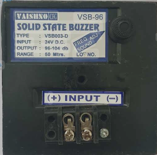
A 24V buzzer is an audio signaling device designed to operate at a 24-volt DC power supply. It produces sound when an electrical current passes through it, making it an essential component in various systems requiring audible alerts. The buzzer is widely used in industrial equipment, security systems, home automation, and other applications where sound-based notifications are necessary.
Explore Projects Built with 24V Buzzer
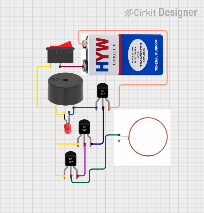
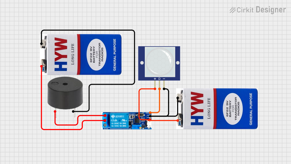
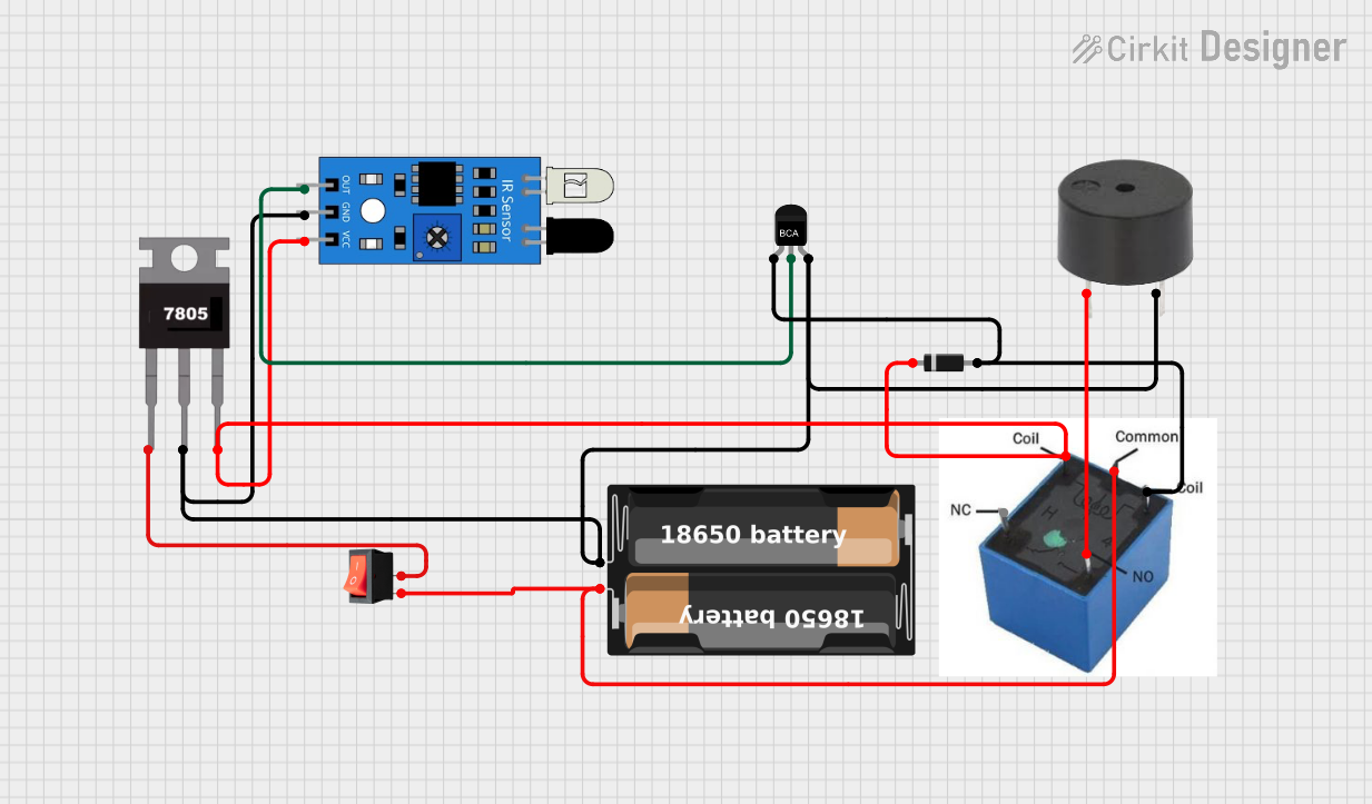

Explore Projects Built with 24V Buzzer
Common Applications:
- Alarm systems (e.g., fire alarms, intrusion alarms)
- Industrial machinery alerts
- Notification systems in home automation
- Automotive warning systems
- Timers and reminders in consumer electronics
Technical Specifications
Below are the key technical details of a standard 24V buzzer:
| Parameter | Specification |
|---|---|
| Operating Voltage | 24V DC |
| Operating Current | Typically 10-30 mA |
| Sound Output Level | 85-100 dB (at 10 cm distance) |
| Frequency Range | 2 kHz to 4 kHz (varies by model) |
| Operating Temperature | -20°C to +60°C |
| Dimensions | Varies (e.g., 30mm diameter, 20mm height) |
| Mounting Type | Panel mount or PCB mount |
Pin Configuration
The 24V buzzer typically has two pins for electrical connections:
| Pin | Description |
|---|---|
| Positive (+) | Connect to the 24V DC power supply (Vcc) |
| Negative (-) | Connect to ground (GND) |
Usage Instructions
How to Use the 24V Buzzer in a Circuit
- Power Supply: Ensure a stable 24V DC power source is available. The buzzer will not function properly if the voltage is significantly lower or higher than 24V.
- Connection:
- Connect the positive pin of the buzzer to the 24V power supply.
- Connect the negative pin to the ground of the circuit.
- Control: To control the buzzer, you can use a switch, relay, or a microcontroller (e.g., Arduino UNO) to turn it on or off.
Example Circuit with Arduino UNO
The 24V buzzer can be controlled using an Arduino UNO and a transistor to handle the higher voltage. Below is an example:
Circuit Components:
- 24V buzzer
- NPN transistor (e.g., 2N2222)
- 1 kΩ resistor
- 24V DC power supply
- Arduino UNO
Circuit Diagram:
- Connect the positive pin of the buzzer to the 24V power supply.
- Connect the negative pin of the buzzer to the collector of the NPN transistor.
- Connect the emitter of the transistor to ground.
- Place a 1 kΩ resistor between the base of the transistor and a digital pin on the Arduino (e.g., pin 9).
- Connect the ground of the Arduino to the ground of the 24V power supply.
Arduino Code:
// Define the pin connected to the transistor base
const int buzzerPin = 9;

void setup() {
  pinMode(buzzerPin, OUTPUT); // Set the pin as an output
}

void loop() {
  digitalWrite(buzzerPin, HIGH); // Turn the buzzer ON
  delay(1000);                   // Wait for 1 second
  digitalWrite(buzzerPin, LOW);  // Turn the buzzer OFF
  delay(1000);                   // Wait for 1 second
}
Important Considerations:
- Voltage Compatibility: Ensure the buzzer is rated for 24V. Using a lower or higher voltage may damage the component or reduce its performance.
- Current Limitation: Verify that the power supply can provide sufficient current (10-30 mA) for the buzzer.
- Noise Level: The buzzer produces a loud sound (85-100 dB). Avoid placing it near sensitive areas or where noise may be disruptive.
- Polarity: Always connect the positive and negative pins correctly to avoid damage.
Troubleshooting and FAQs
Common Issues and Solutions:
Buzzer Does Not Produce Sound:
- Check the power supply voltage. Ensure it is 24V DC.
- Verify the connections. Ensure the positive and negative pins are connected correctly.
- Test the buzzer with a direct 24V power source to confirm it is functional.
Buzzer Produces Weak or Intermittent Sound:
- Ensure the power supply can provide sufficient current (10-30 mA).
- Check for loose or faulty connections in the circuit.
Buzzer is Too Loud:
- Use a resistor in series with the buzzer to reduce the current and lower the sound level.
- Consider using a lower-decibel buzzer if the application allows.
Buzzer Overheats:
- Verify that the operating voltage does not exceed 24V.
- Check for continuous operation beyond the recommended duty cycle (if specified by the manufacturer).
FAQs:
Q1: Can I use a 24V buzzer with a 12V power supply?
A1: No, a 12V power supply will not provide sufficient voltage for the buzzer to operate correctly. Use a 24V DC power source.
Q2: Can I connect the buzzer directly to an Arduino UNO?
A2: No, the Arduino UNO operates at 5V and cannot directly drive a 24V buzzer. Use a transistor or relay to control the buzzer.
Q3: Is the buzzer polarity-sensitive?
A3: Yes, the buzzer has a positive (+) and negative (-) pin. Reversing the polarity may damage the component.
Q4: Can I use the buzzer outdoors?
A4: Only if the buzzer is rated for outdoor use or is enclosed in a weatherproof housing. Check the manufacturer's specifications.