Cirkit Designer Logo
Cirkit Designer
Your all-in-one circuit design IDE
Home / 
Component Documentation

How to Use Torque Sensor: Examples, Pinouts, and Specs
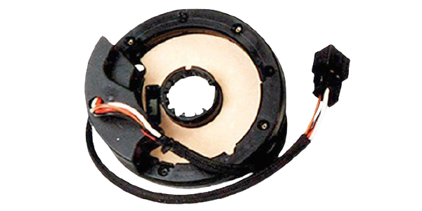
Image of Torque Sensor
Cirkit Designer LogoDesign with Torque Sensor in Cirkit Designer

Introduction

A torque sensor is a device that measures and records the torque on a rotating system, such as an engine or a crankshaft. Torque sensors are essential in various applications, including automotive testing, industrial machinery, and robotics. They provide critical data for performance analysis, quality control, and system optimization.

Explore Projects Built with Torque Sensor
Use Cirkit Designer to design, explore, and prototype these projects online. Some projects support real-time simulation. Click "Open Project" to start designing instantly!
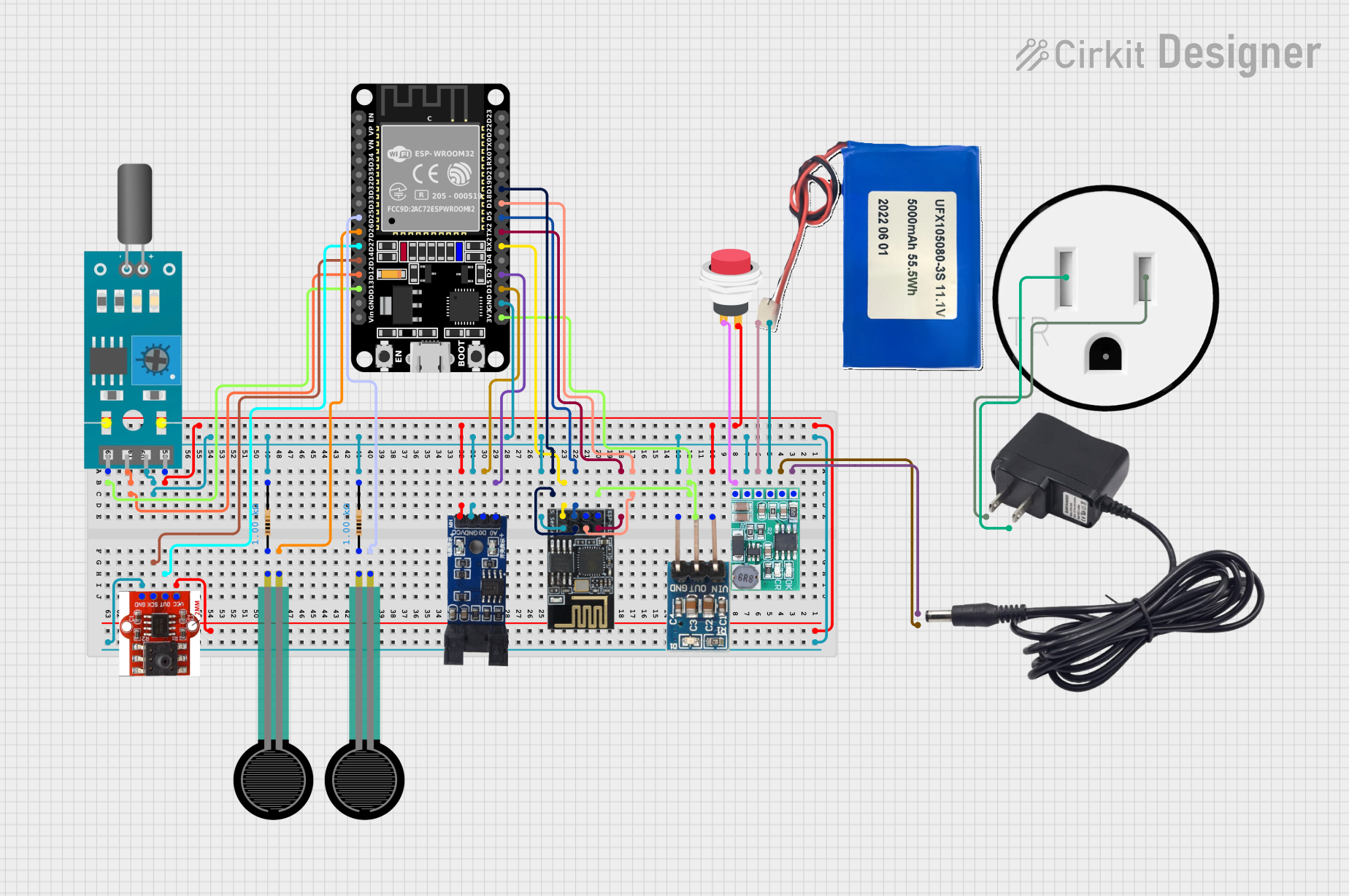
ESP32 and ESP8266 Wi-Fi Controlled Sensor Hub with Battery Backup
Image of baby guard: A project utilizing Torque Sensor in a practical application
This circuit is a sensor monitoring and data transmission system powered by a Li-ion battery and a 12V adapter. It includes various sensors (tilt, optical encoder, force sensing resistors, and air pressure) connected to an ESP32 microcontroller, which reads sensor data and transmits it via a WiFi module (ESP8266-01). The system is designed to provide real-time sensor data over a WiFi network.
Cirkit Designer LogoOpen Project in Cirkit Designer
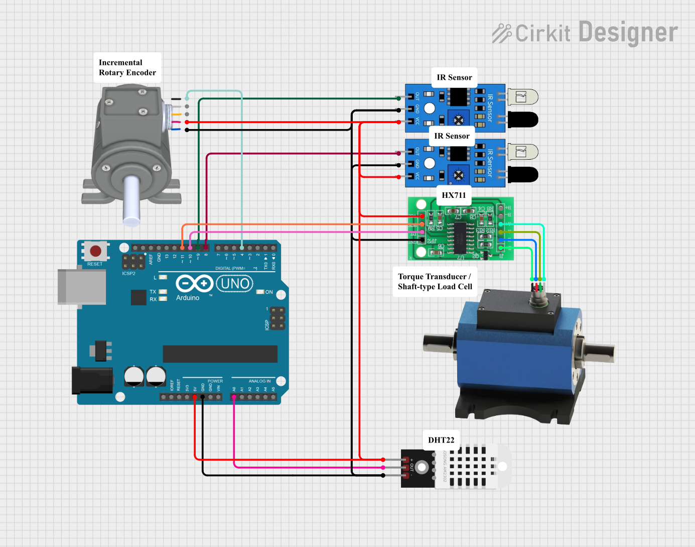
Arduino UNO-Based Multi-Sensor Data Acquisition System with Torque and Rotary Encoder Integration
Image of Transmisison Efficiency Test: A project utilizing Torque Sensor in a practical application
This circuit is designed to interface various sensors with an Arduino UNO for data acquisition and processing. It includes a torque transducer connected through an HX711 bridge sensor interface, a rotary encoder, two IR sensors, and a DHT22 temperature and humidity sensor. The Arduino UNO collects data from these sensors and can be programmed to process and utilize this data for various applications.
Cirkit Designer LogoOpen Project in Cirkit Designer
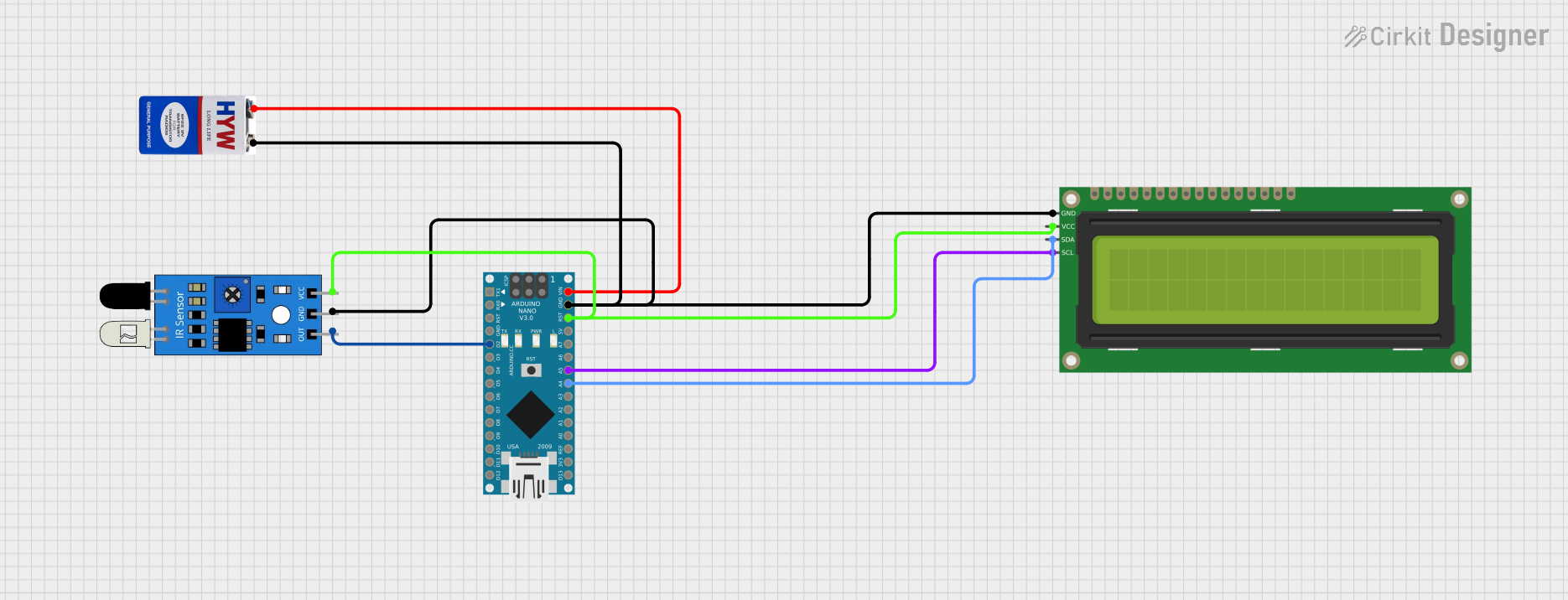
Arduino Nano-Based Tachometer with IR Sensor and I2C LCD Display
Image of tachometer : A project utilizing Torque Sensor in a practical application
This circuit functions as a tachometer using an Arduino Nano to measure the rotation of a wheel via an IR sensor. The IR sensor's output is connected to the Arduino's digital pin D2, and rotation counts are displayed on a 16x2 I2C LCD connected to the I2C pins A4 (SDA) and A5 (SCL). The circuit is powered by a 9V battery connected to the Arduino's VIN pin, and all components share a common ground.
Cirkit Designer LogoOpen Project in Cirkit Designer
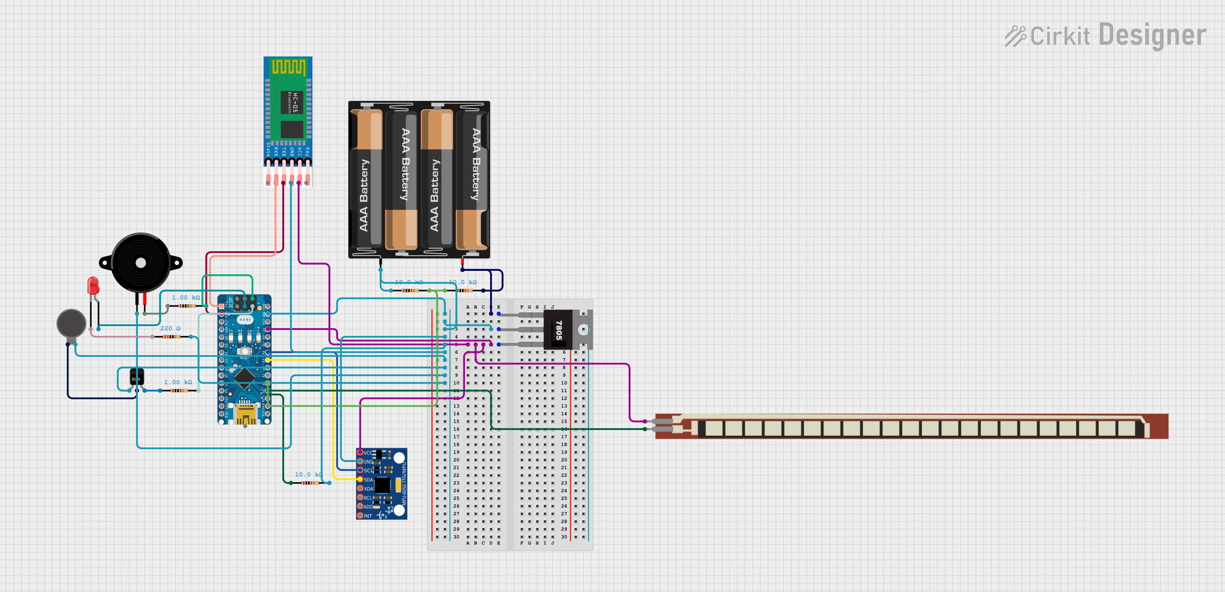
Arduino Nano-Based Wearable Gesture Control Interface with Bluetooth Connectivity
Image of spine: A project utilizing Torque Sensor in a practical application
This is a battery-powered sensor system with Bluetooth communication, featuring an Arduino Nano for control, an MPU-6050 for motion sensing, and an HC-05 module for wireless data transmission. It includes a vibration motor for haptic feedback, a flex resistor as an additional sensor, and a piezo speaker and LED for alerts or status indication.
Cirkit Designer LogoOpen Project in Cirkit Designer

Explore Projects Built with Torque Sensor

Use Cirkit Designer to design, explore, and prototype these projects online. Some projects support real-time simulation. Click "Open Project" to start designing instantly!
Image of baby guard: A project utilizing Torque Sensor in a practical application
ESP32 and ESP8266 Wi-Fi Controlled Sensor Hub with Battery Backup
This circuit is a sensor monitoring and data transmission system powered by a Li-ion battery and a 12V adapter. It includes various sensors (tilt, optical encoder, force sensing resistors, and air pressure) connected to an ESP32 microcontroller, which reads sensor data and transmits it via a WiFi module (ESP8266-01). The system is designed to provide real-time sensor data over a WiFi network.
Cirkit Designer LogoOpen Project in Cirkit Designer
Image of Transmisison Efficiency Test: A project utilizing Torque Sensor in a practical application
Arduino UNO-Based Multi-Sensor Data Acquisition System with Torque and Rotary Encoder Integration
This circuit is designed to interface various sensors with an Arduino UNO for data acquisition and processing. It includes a torque transducer connected through an HX711 bridge sensor interface, a rotary encoder, two IR sensors, and a DHT22 temperature and humidity sensor. The Arduino UNO collects data from these sensors and can be programmed to process and utilize this data for various applications.
Cirkit Designer LogoOpen Project in Cirkit Designer
Image of tachometer : A project utilizing Torque Sensor in a practical application
Arduino Nano-Based Tachometer with IR Sensor and I2C LCD Display
This circuit functions as a tachometer using an Arduino Nano to measure the rotation of a wheel via an IR sensor. The IR sensor's output is connected to the Arduino's digital pin D2, and rotation counts are displayed on a 16x2 I2C LCD connected to the I2C pins A4 (SDA) and A5 (SCL). The circuit is powered by a 9V battery connected to the Arduino's VIN pin, and all components share a common ground.
Cirkit Designer LogoOpen Project in Cirkit Designer
Image of spine: A project utilizing Torque Sensor in a practical application
Arduino Nano-Based Wearable Gesture Control Interface with Bluetooth Connectivity
This is a battery-powered sensor system with Bluetooth communication, featuring an Arduino Nano for control, an MPU-6050 for motion sensing, and an HC-05 module for wireless data transmission. It includes a vibration motor for haptic feedback, a flex resistor as an additional sensor, and a piezo speaker and LED for alerts or status indication.
Cirkit Designer LogoOpen Project in Cirkit Designer

Technical Specifications

Key Technical Details

Parameter Value
Supply Voltage 5V DC
Output Signal Analog (0-5V)
Measurement Range 0-100 Nm
Accuracy ±0.5% of full scale
Operating Temperature -20°C to 85°C
Response Time < 1 ms
Interface 3-wire (Vcc, GND, Signal)

Pin Configuration and Descriptions

Pin Number Pin Name Description
1 Vcc Power supply (5V DC)
2 GND Ground
3 Signal Analog output signal (0-5V)

Usage Instructions

How to Use the Component in a Circuit

  1. Power Supply: Connect the Vcc pin to a 5V DC power supply.
  2. Ground: Connect the GND pin to the ground of the power supply.
  3. Signal Output: Connect the Signal pin to an analog input pin on a microcontroller (e.g., Arduino UNO).

Important Considerations and Best Practices

  • Calibration: Ensure the torque sensor is calibrated before use to maintain accuracy.
  • Mounting: Securely mount the sensor to avoid vibrations and mechanical stress that could affect readings.
  • Temperature: Operate within the specified temperature range to prevent damage and ensure accurate measurements.
  • Shielding: Use shielded cables to minimize electrical noise and interference.

Example Circuit Diagram

Torque Sensor Circuit Diagram

Arduino UNO Example Code

// Torque Sensor Example Code
// This code reads the analog signal from the torque sensor and prints the
// torque value to the Serial Monitor.

const int torqueSensorPin = A0; // Analog pin connected to the Signal pin
float torqueValue = 0;          // Variable to store the torque value

void setup() {
  Serial.begin(9600); // Initialize serial communication at 9600 baud rate
}

void loop() {
  int sensorValue = analogRead(torqueSensorPin); // Read the analog value
  torqueValue = (sensorValue / 1023.0) * 100;    // Convert to torque (0-100 Nm)
  
  Serial.print("Torque: ");
  Serial.print(torqueValue);
  Serial.println(" Nm");
  
  delay(500); // Wait for 500 milliseconds before the next reading
}

Troubleshooting and FAQs

Common Issues Users Might Face

  1. Inaccurate Readings:

    • Solution: Ensure the sensor is properly calibrated and securely mounted. Check for any mechanical stress or vibrations that could affect the readings.
  2. No Output Signal:

    • Solution: Verify the power supply connections (Vcc and GND). Ensure the Signal pin is correctly connected to the analog input of the microcontroller.
  3. Fluctuating Readings:

    • Solution: Use shielded cables to minimize electrical noise. Ensure the sensor is operating within the specified temperature range.

FAQs

Q1: How do I calibrate the torque sensor?

  • A1: Follow the manufacturer's calibration procedure, which typically involves applying known torque values and adjusting the sensor output accordingly.

Q2: Can I use the torque sensor with a different microcontroller?

  • A2: Yes, the torque sensor can be used with any microcontroller that has an analog input pin and operates at 5V DC.

Q3: What should I do if the sensor gets damaged?

  • A3: If the sensor is physically damaged, it is recommended to replace it. For minor issues, consult the manufacturer's troubleshooting guide.

Q4: How often should I recalibrate the sensor?

  • A4: Recalibration frequency depends on the application and usage. For critical applications, recalibrate periodically as recommended by the manufacturer.

This documentation provides a comprehensive guide to understanding, using, and troubleshooting a torque sensor. Whether you are a beginner or an experienced user, following these guidelines will help you achieve accurate and reliable torque measurements in your projects.