Cirkit Designer
Your all-in-one circuit design IDE
Home /
Component Documentation
How to Use Arduino Pro Mini v13: Examples, Pinouts, and Specs
Introduction
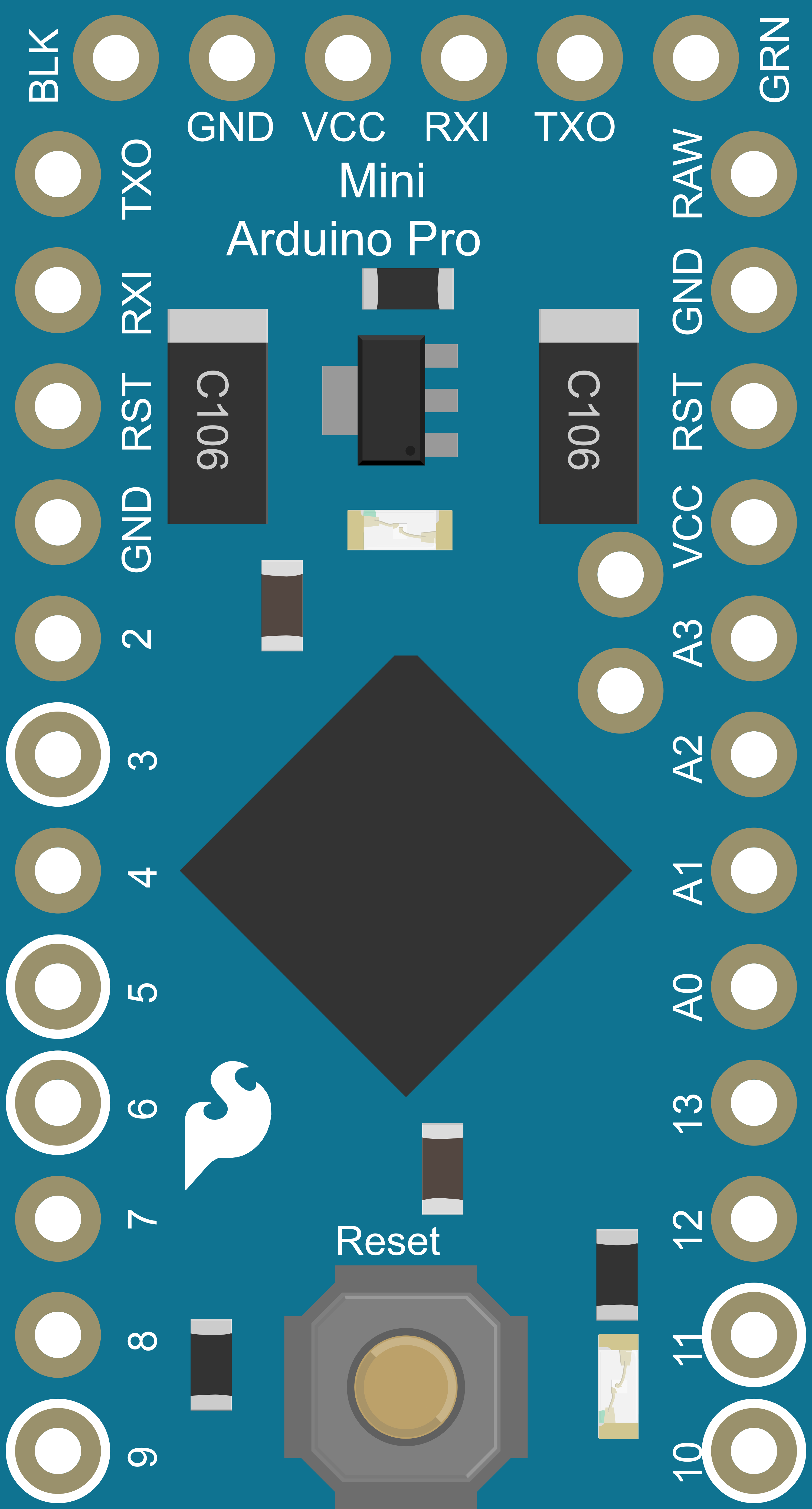
The Arduino Pro Mini v13 is a compact microcontroller board based on the ATmega328P, which is the same microcontroller used in the popular Arduino Uno. It is designed for advanced users who require a small, lightweight, and low-power board for embedded projects. The Pro Mini is ideal for applications where space is at a premium, such as wearable technology, portable instruments, and custom embedded systems.
Explore Projects Built with Arduino Pro Mini v13
Arduino Pro Mini-Based Smart Home Automation with ADXL345 and RS232 Communication
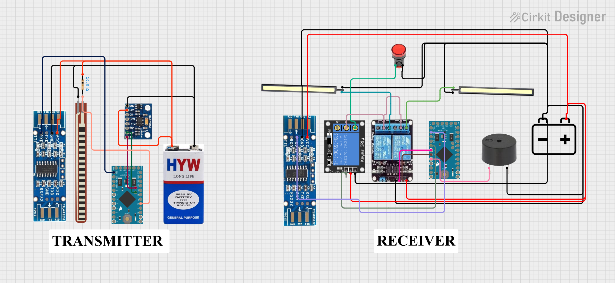
This circuit features two Arduino Pro Mini microcontrollers interfacing with various sensors and actuators. One Arduino reads data from an ADXL345 accelerometer and communicates with an RS232 module, while the other controls a 2-channel relay to manage two 12V LEDs, a 1-channel relay to control a red lamp, and a buzzer. Power is supplied by 9V and 12V batteries.
Arduino Pro Mini Based CAN Bus Interface with OLED Display
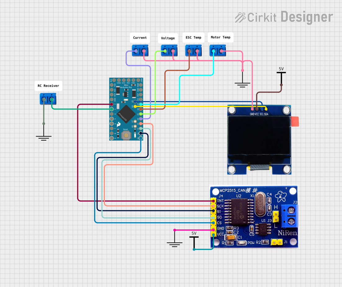
This circuit features an Arduino Pro Mini connected to an OLED display via I2C communication (SDA and SCL lines). The Arduino is also interfaced with an MCP2515 CAN controller, indicating the circuit's capability to communicate over a CAN network. Additionally, there are several terminal PCBs connected to various analog and digital pins of the Arduino, likely for sensor inputs or output controls.
Arduino Pro Mini-Based Battery-Powered Temperature and Laser Display System
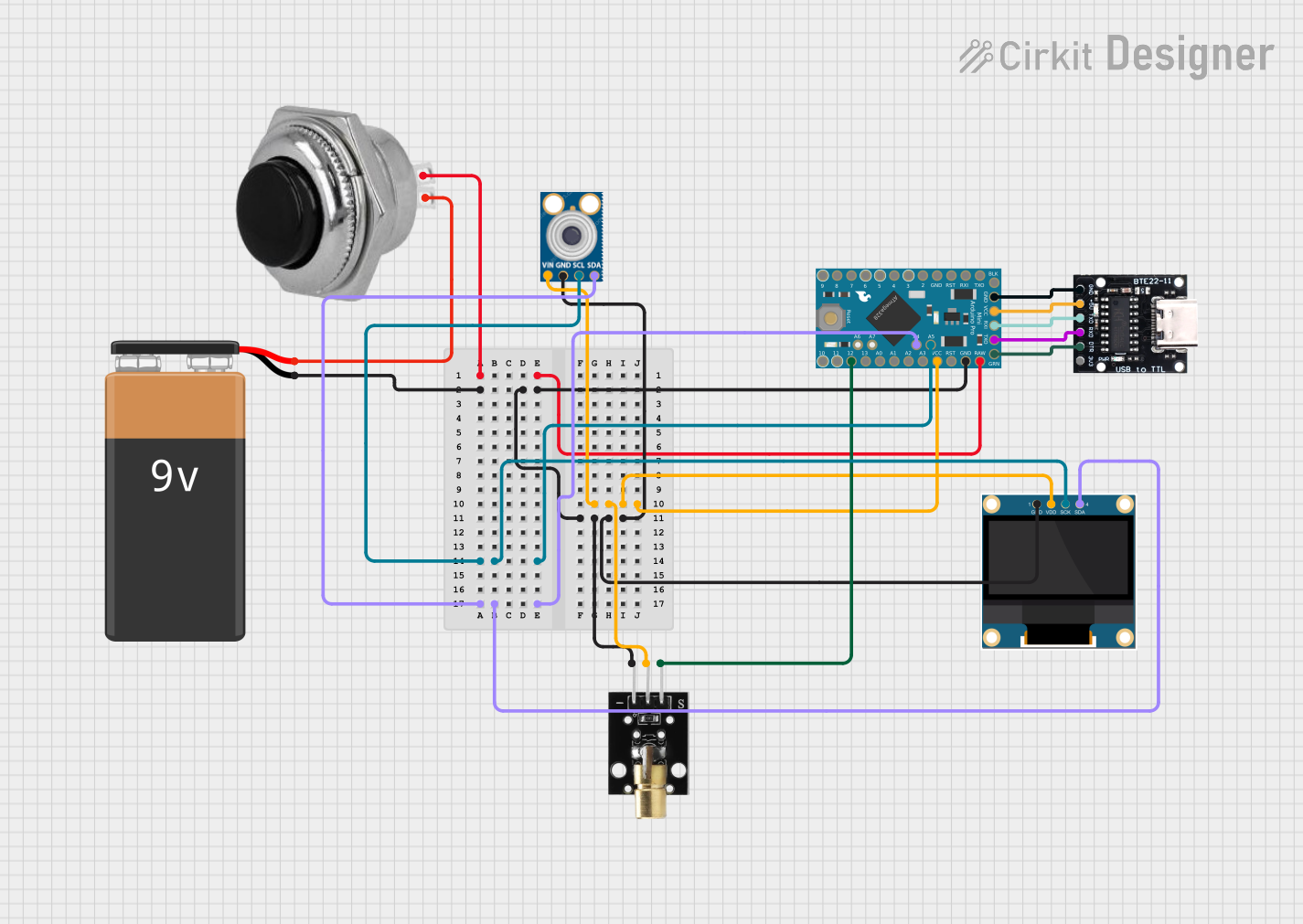
This circuit features an Arduino Pro Mini microcontroller interfaced with a USB Serial TTL for programming and power, a momentary switch for user input, and a 9V battery for power supply. It includes a KY-008 laser emitter, a 0.96" OLED display, and an MLX90614 temperature sensor, all connected to the Arduino for a potential temperature measurement and display application.
Arduino Pro Mini Based GPS and Temperature Tracking System with Wireless Communication
This circuit features an Arduino Pro Mini as the central microcontroller, interfaced with a DS18B20 temperature sensor, a GPS NEO 6M module for location tracking, an ADXL345 accelerometer for motion detection, and an NRF24L01 module for wireless communication. The Arduino is powered by a 18650 Li-Ion battery through a voltage regulator, ensuring a stable power supply. A pushbutton is connected to the Arduino for user input, and resistors are used for pull-ups and current limiting purposes.
Explore Projects Built with Arduino Pro Mini v13
Arduino Pro Mini-Based Smart Home Automation with ADXL345 and RS232 Communication
This circuit features two Arduino Pro Mini microcontrollers interfacing with various sensors and actuators. One Arduino reads data from an ADXL345 accelerometer and communicates with an RS232 module, while the other controls a 2-channel relay to manage two 12V LEDs, a 1-channel relay to control a red lamp, and a buzzer. Power is supplied by 9V and 12V batteries.
Arduino Pro Mini Based CAN Bus Interface with OLED Display
This circuit features an Arduino Pro Mini connected to an OLED display via I2C communication (SDA and SCL lines). The Arduino is also interfaced with an MCP2515 CAN controller, indicating the circuit's capability to communicate over a CAN network. Additionally, there are several terminal PCBs connected to various analog and digital pins of the Arduino, likely for sensor inputs or output controls.
Arduino Pro Mini-Based Battery-Powered Temperature and Laser Display System
This circuit features an Arduino Pro Mini microcontroller interfaced with a USB Serial TTL for programming and power, a momentary switch for user input, and a 9V battery for power supply. It includes a KY-008 laser emitter, a 0.96" OLED display, and an MLX90614 temperature sensor, all connected to the Arduino for a potential temperature measurement and display application.
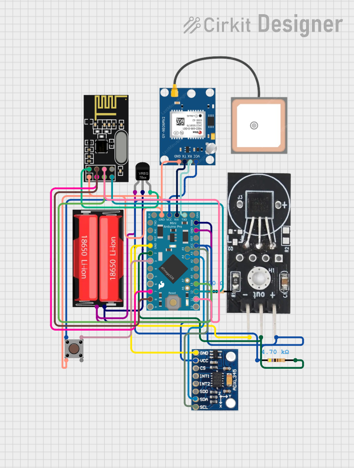
Arduino Pro Mini Based GPS and Temperature Tracking System with Wireless Communication
This circuit features an Arduino Pro Mini as the central microcontroller, interfaced with a DS18B20 temperature sensor, a GPS NEO 6M module for location tracking, an ADXL345 accelerometer for motion detection, and an NRF24L01 module for wireless communication. The Arduino is powered by a 18650 Li-Ion battery through a voltage regulator, ensuring a stable power supply. A pushbutton is connected to the Arduino for user input, and resistors are used for pull-ups and current limiting purposes.
Common Applications and Use Cases
- Wearable devices
- Portable electronics
- Prototyping IoT devices
- High-altitude balloon experiments
- Small robotics projects
- Custom embedded systems
Technical Specifications
Key Technical Details
- Microcontroller: ATmega328P
- Operating Voltage: 3.3V or 5V (depending on the model)
- Input Voltage (recommended): 5V - 12V
- Digital I/O Pins: 14 (of which 6 provide PWM output)
- Analog Input Pins: 6
- DC Current per I/O Pin: 40 mA
- Flash Memory: 32 KB (ATmega328P) of which 0.5 KB used by bootloader
- SRAM: 2 KB (ATmega328P)
- EEPROM: 1 KB (ATmega328P)
- Clock Speed: 8 MHz (3.3V model) or 16 MHz (5V model)
Pin Configuration and Descriptions
| Pin Number | Function | Description |
|---|---|---|
| 1 | RESET | Used to reset the microcontroller |
| 2-3 | D0 (RX), D1 (TX) | Serial communication pins |
| 4-9 | D2-D7 | Digital pins, D3/D5/D6 provide PWM output |
| 10-15 | D8-D13 | Digital pins, D9/D10/D11 provide PWM output |
| 16-21 | A0-A5 | Analog input pins or digital I/O |
| 22 | AREF | Analog reference voltage for ADC |
| 23-26 | GND | Ground pins |
| 27-28 | RAW, VCC | RAW: Unregulated input voltage, VCC: Regulated operating voltage |
Usage Instructions
How to Use the Component in a Circuit
- Powering the Board: Connect a power source to the RAW pin (if using an unregulated power supply) or the VCC pin (if using a regulated 3.3V or 5V supply).
- Programming the Board: Use an external USB-to-serial adapter to connect the D0 (RX) and D1 (TX) pins to your computer for uploading sketches.
- Connecting I/O: Attach sensors, actuators, or other peripherals to the digital and analog pins as required by your project.
- Resetting the Board: If necessary, the RESET pin can be connected to a pushbutton to manually reset the microcontroller.
Important Considerations and Best Practices
- Always ensure that the power supply voltage matches the board's requirements (3.3V or 5V).
- Do not exceed the maximum current rating of the I/O pins to prevent damage to the board.
- When using PWM outputs, ensure that the connected devices are compatible with the PWM frequency.
- Use pull-up or pull-down resistors with digital inputs to ensure a stable state when no input is present.
Troubleshooting and FAQs
Common Issues Users Might Face
- Board not responding: Ensure that the board is correctly powered and that the USB-to-serial adapter is functioning.
- Sketch not uploading: Check the connections between the USB-to-serial adapter and the Pro Mini, and ensure the correct board and port are selected in the Arduino IDE.
- Unexpected behavior: Verify that all peripherals are correctly connected and that the code uploaded to the board is functioning as intended.
Solutions and Tips for Troubleshooting
- Double-check wiring and solder joints for any loose connections or shorts.
- Use a multimeter to verify voltage levels at the power supply and I/O pins.
- Ensure that the bootloader is correctly installed on the ATmega328P. If not, you may need to burn the bootloader using an AVR ISP programmer.
Example Code for Arduino UNO
// Blink an LED connected to pin 13

void setup() {
  pinMode(13, OUTPUT); // Set pin 13 as an output
}

void loop() {
  digitalWrite(13, HIGH);   // Turn the LED on
  delay(1000);              // Wait for a second
  digitalWrite(13, LOW);    // Turn the LED off
  delay(1000);              // Wait for a second
}
Note: The above code is for demonstration purposes and assumes an LED is connected to pin 13 with a suitable current-limiting resistor.
For more advanced usage and additional examples, refer to the Arduino community forums and the extensive library of shared projects available online.