How to Use TRANSFORMER: Examples, Pinouts, and Specs
Introduction
A transformer is a passive electrical device that transfers electrical energy between two or more circuits through electromagnetic induction. Transformers are essential components in electrical systems, used to step up (increase) or step down (decrease) voltage levels in alternating current (AC) circuits. They are widely used in power distribution, audio systems, and various electronic appliances to ensure the safe and efficient operation of electrical equipment.
Explore Projects Built with TRANSFORMER
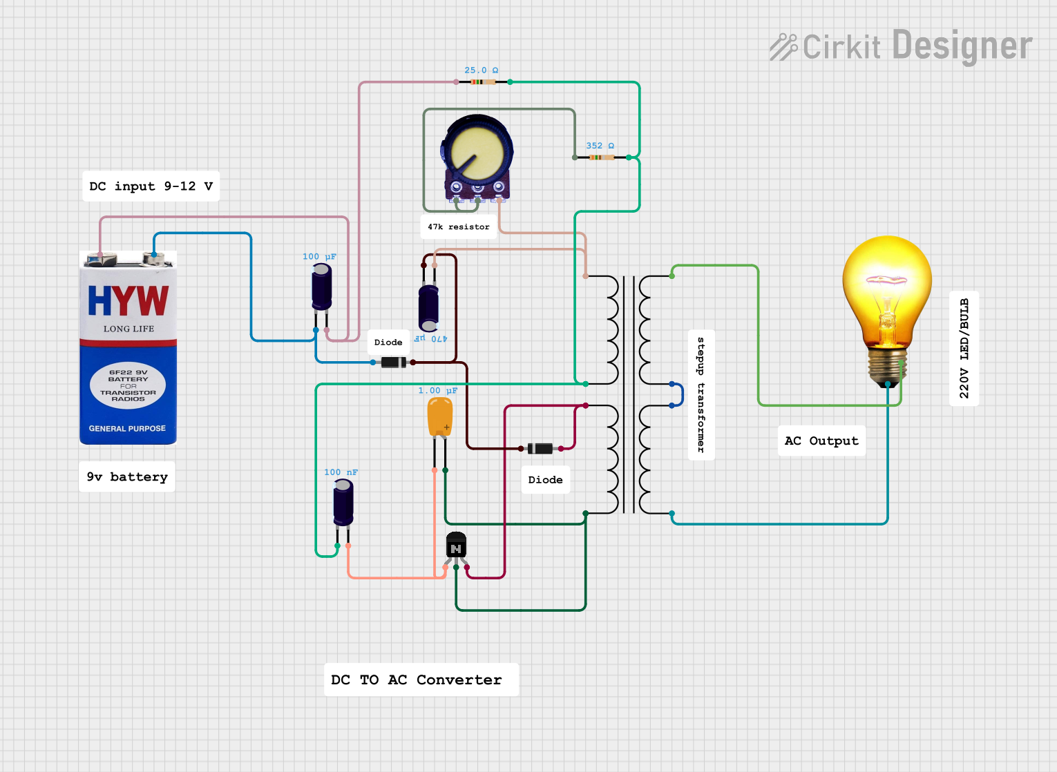


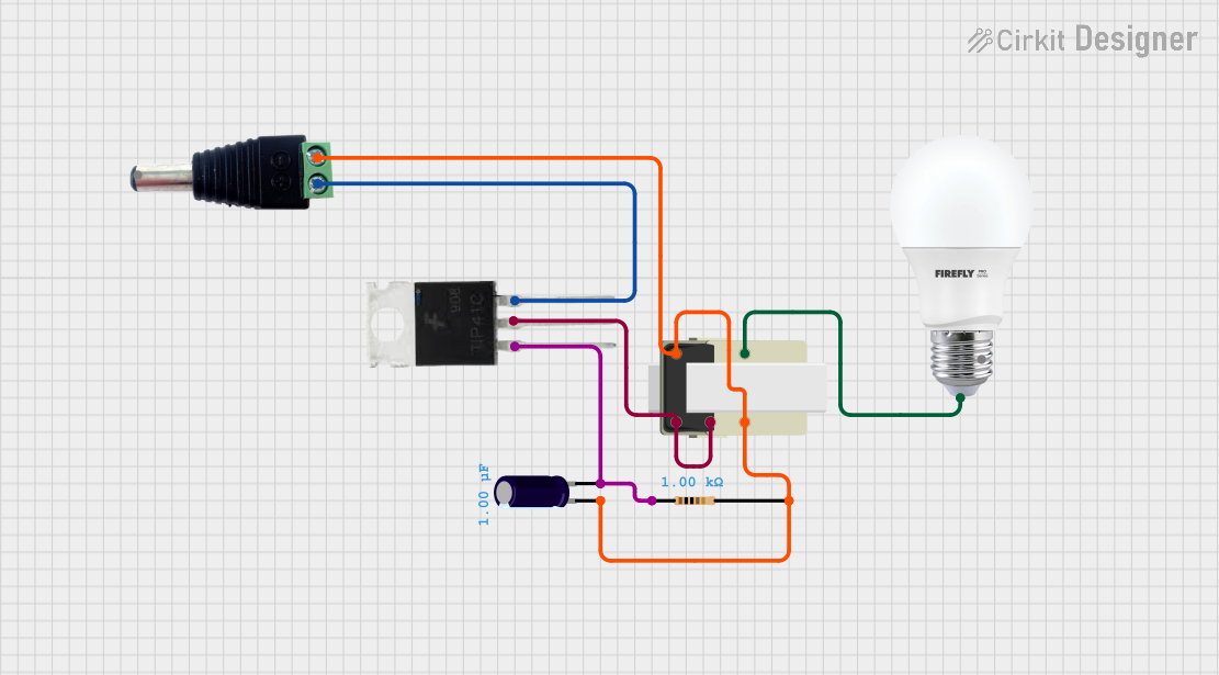
Explore Projects Built with TRANSFORMER
Common Applications and Use Cases
- Power Distribution: Transformers are used to step down the high voltage from power stations to lower levels suitable for home and business use.
- Impedance Matching: Audio transformers match the impedance of loudspeakers to the optimal load of amplifiers.
- Isolation: Isolation transformers provide electrical isolation to sensitive equipment, enhancing safety and noise reduction.
- Voltage Conversion: In electronic devices, transformers convert the 110-240V mains voltage to lower levels suitable for the internal circuitry.
Technical Specifications
Key Technical Details
- Voltage Rating: The maximum input (primary) and output (secondary) voltages the transformer can handle.
- Current Rating: The maximum current the transformer can carry without overheating.
- Power Rating: The total amount of power (in VA or Watts) the transformer can handle.
- Frequency Range: The range of frequencies over which the transformer operates efficiently.
- Efficiency: The ratio of output power to input power, typically expressed as a percentage.
- Isolation Voltage: The maximum voltage that can be applied across the transformer's isolation barrier.
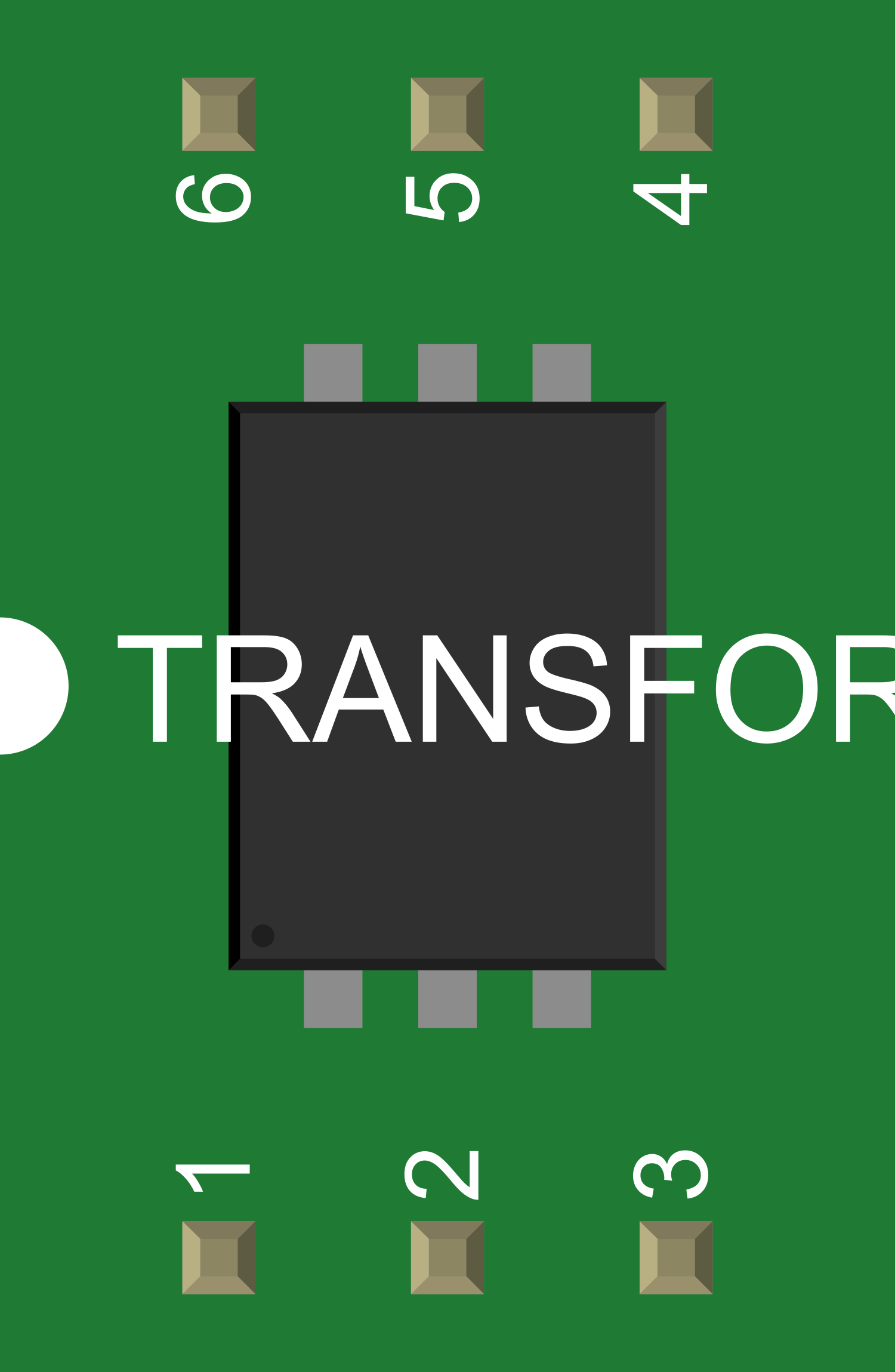
Pin Configuration and Descriptions
| Pin Number | Description | Notes |
|---|---|---|
| P1 | Primary winding start | Connect to AC voltage source |
| P2 | Primary winding end | |
| S1 | Secondary winding start | Output AC voltage (stepped down or up) |
| S2 | Secondary winding end |
Usage Instructions
How to Use the Transformer in a Circuit
- Identify Transformer Ratings: Ensure the transformer's voltage and current ratings match your circuit requirements.
- Circuit Integration: Connect the primary winding (P1 and P2) to the AC voltage source you wish to transform.
- Load Connection: Connect the secondary winding (S1 and S2) to the load that requires the transformed voltage.
- Grounding: Properly ground the transformer to prevent electrical shock and interference.
- Testing: Before full operation, test the transformer with a multimeter to ensure the correct output voltage is present.
Important Considerations and Best Practices
- Overloading: Never exceed the power rating of the transformer to avoid overheating and potential failure.
- Cooling: Ensure adequate cooling for the transformer, especially in high-power applications.
- Mounting: Securely mount the transformer to avoid vibrations and potential damage.
- Insulation: Maintain proper insulation between the windings and between the transformer and other components.
Troubleshooting and FAQs
Common Issues Users Might Face
- Overheating: Caused by overloading or poor ventilation. Ensure the transformer is not exceeding its rated capacity and has adequate airflow.
- Humming Noise: Can be due to loose laminations or mountings. Tighten any loose parts and ensure the transformer is securely mounted.
- Low Output Voltage: This could be due to a poor connection or an overloaded secondary circuit. Check connections and load requirements.
Solutions and Tips for Troubleshooting
- Check Connections: Loose connections can cause various issues. Ensure all connections are secure.
- Measure Input/Output Voltage: Use a multimeter to verify that the input and output voltages are within specifications.
- Inspect for Physical Damage: Look for signs of burning, corrosion, or other physical damage that might affect performance.
FAQs
Q: Can I use a transformer to convert DC to AC or vice versa? A: No, transformers only work with AC voltages. For DC, you would need a converter or inverter.
Q: How do I know if my transformer is working properly? A: Measure the input and output voltages with a multimeter. The output should match the transformer's specifications when the correct input is applied.
Q: Can transformers affect power quality? A: Yes, poor-quality transformers can introduce losses and distortions. Always use a transformer that meets the required standards and specifications for your application.
Example Code for Arduino UNO
Transformers are not directly interfaced with microcontrollers like the Arduino UNO since they operate with AC voltages and microcontrollers work with DC. However, if you are using a transformer to power an Arduino project, ensure that the output voltage of the transformer is rectified, filtered, and regulated to the appropriate DC voltage required by the Arduino (typically 5V or 3.3V).
// No direct code example is applicable for a transformer as it is an AC component.
// Always ensure that the output from the transformer is converted to DC before
// connecting to any microcontroller or digital circuit.
Remember, safety is paramount when dealing with transformers and high voltages. Always follow electrical codes and standards, and consult a professional if you are unsure about working with electrical components.