Cirkit Designer Logo
Cirkit Designer
Your all-in-one circuit design IDE
Home / 
Component Documentation

How to Use Adafruit LIS2MDL: Examples, Pinouts, and Specs

Image of Adafruit LIS2MDL
Cirkit Designer LogoDesign with Adafruit LIS2MDL in Cirkit Designer

Introduction

The Adafruit LIS2MDL is a high-precision magnetometer module capable of measuring the Earth's magnetic field in three dimensions. This compact sensor is ideal for applications such as compasses, navigation systems, and for detecting magnetic anomalies. Its versatility is enhanced by its support for both I2C and SPI communication protocols, allowing it to be easily integrated into a wide range of projects, including those based on microcontrollers like the Arduino UNO.

Explore Projects Built with Adafruit LIS2MDL

Use Cirkit Designer to design, explore, and prototype these projects online. Some projects support real-time simulation. Click "Open Project" to start designing instantly!
Teensy 4.1 Based Biometric Data Acquisition System with AD8232 Heart Rate Monitor and LIS3DH Accelerometer
Image of Teensy 4.1 accelerometer: A project utilizing Adafruit LIS2MDL in a practical application
This circuit integrates a Teensy 4.1 microcontroller with an Adafruit LIS3DH Triple-Axis Accelerometer and an AD8232 Heart Rate Monitor. The accelerometer communicates with the Teensy via I2C (SCL and SDA lines), while the heart rate monitor's output and lead-off detection (LO+ and LO-) are connected to the Teensy's analog inputs. The circuit is designed to measure both acceleration and heart rate signals, likely for a wearable or health monitoring device.
Cirkit Designer LogoOpen Project in Cirkit Designer
Arduino Mega 2560-Based Multi-Sensor System with Distance, Magnetometer, and Camera Integration
Image of Junior Design - Sensors: A project utilizing Adafruit LIS2MDL in a practical application
This circuit features an Arduino Mega 2560 microcontroller interfaced with multiple VL53L0X distance sensors, an OV7725 camera module, and an Adafruit LIS3MDL triple-axis magnetometer. The Arduino reads data from these sensors and the camera, likely for a robotics or environmental sensing application, and processes the data for further use or transmission.
Cirkit Designer LogoOpen Project in Cirkit Designer
Arduino Ethernet with LSM303DLHC Accelerometer and Compass Interface
Image of Compass: A project utilizing Adafruit LIS2MDL in a practical application
This circuit connects an Adafruit LSM303DLHC Triple-axis Accelerometer+Magnetometer (Compass) to an Arduino Board Ethernet using I2C communication protocol. The SCL and SDA pins of the sensor are connected to the A5 and A4 pins of the Arduino, respectively, for serial clock and data transfer. The sensor is powered by the Arduino's 5V output, and both devices share a common ground.
Cirkit Designer LogoOpen Project in Cirkit Designer
Arduino UNO R4 WiFi and Adafruit LIS3DH Accelerometer-Based Motion Detection System
Image of circuit: A project utilizing Adafruit LIS2MDL in a practical application
This circuit consists of an Arduino UNO R4 WiFi connected to an Adafruit LIS3DH Triple-Axis Accelerometer via I2C communication. The Arduino reads acceleration data from the LIS3DH sensor and outputs it to the serial monitor for further analysis or processing.
Cirkit Designer LogoOpen Project in Cirkit Designer

Explore Projects Built with Adafruit LIS2MDL

Use Cirkit Designer to design, explore, and prototype these projects online. Some projects support real-time simulation. Click "Open Project" to start designing instantly!
Image of Teensy 4.1 accelerometer: A project utilizing Adafruit LIS2MDL in a practical application
Teensy 4.1 Based Biometric Data Acquisition System with AD8232 Heart Rate Monitor and LIS3DH Accelerometer
This circuit integrates a Teensy 4.1 microcontroller with an Adafruit LIS3DH Triple-Axis Accelerometer and an AD8232 Heart Rate Monitor. The accelerometer communicates with the Teensy via I2C (SCL and SDA lines), while the heart rate monitor's output and lead-off detection (LO+ and LO-) are connected to the Teensy's analog inputs. The circuit is designed to measure both acceleration and heart rate signals, likely for a wearable or health monitoring device.
Cirkit Designer LogoOpen Project in Cirkit Designer
Image of Junior Design - Sensors: A project utilizing Adafruit LIS2MDL in a practical application
Arduino Mega 2560-Based Multi-Sensor System with Distance, Magnetometer, and Camera Integration
This circuit features an Arduino Mega 2560 microcontroller interfaced with multiple VL53L0X distance sensors, an OV7725 camera module, and an Adafruit LIS3MDL triple-axis magnetometer. The Arduino reads data from these sensors and the camera, likely for a robotics or environmental sensing application, and processes the data for further use or transmission.
Cirkit Designer LogoOpen Project in Cirkit Designer
Image of Compass: A project utilizing Adafruit LIS2MDL in a practical application
Arduino Ethernet with LSM303DLHC Accelerometer and Compass Interface
This circuit connects an Adafruit LSM303DLHC Triple-axis Accelerometer+Magnetometer (Compass) to an Arduino Board Ethernet using I2C communication protocol. The SCL and SDA pins of the sensor are connected to the A5 and A4 pins of the Arduino, respectively, for serial clock and data transfer. The sensor is powered by the Arduino's 5V output, and both devices share a common ground.
Cirkit Designer LogoOpen Project in Cirkit Designer
Image of circuit: A project utilizing Adafruit LIS2MDL in a practical application
Arduino UNO R4 WiFi and Adafruit LIS3DH Accelerometer-Based Motion Detection System
This circuit consists of an Arduino UNO R4 WiFi connected to an Adafruit LIS3DH Triple-Axis Accelerometer via I2C communication. The Arduino reads acceleration data from the LIS3DH sensor and outputs it to the serial monitor for further analysis or processing.
Cirkit Designer LogoOpen Project in Cirkit Designer

Technical Specifications

Key Features

  • Magnetic Field Range: ±50 gauss
  • Resolution: Up to 16-bit
  • Communication Interfaces: I2C (up to 1MHz), SPI (up to 10MHz)
  • Operating Voltage: 2.5V to 5.5V
  • Operating Temperature Range: -40°C to +85°C
  • Current Consumption: 0.5 µA in low-power mode

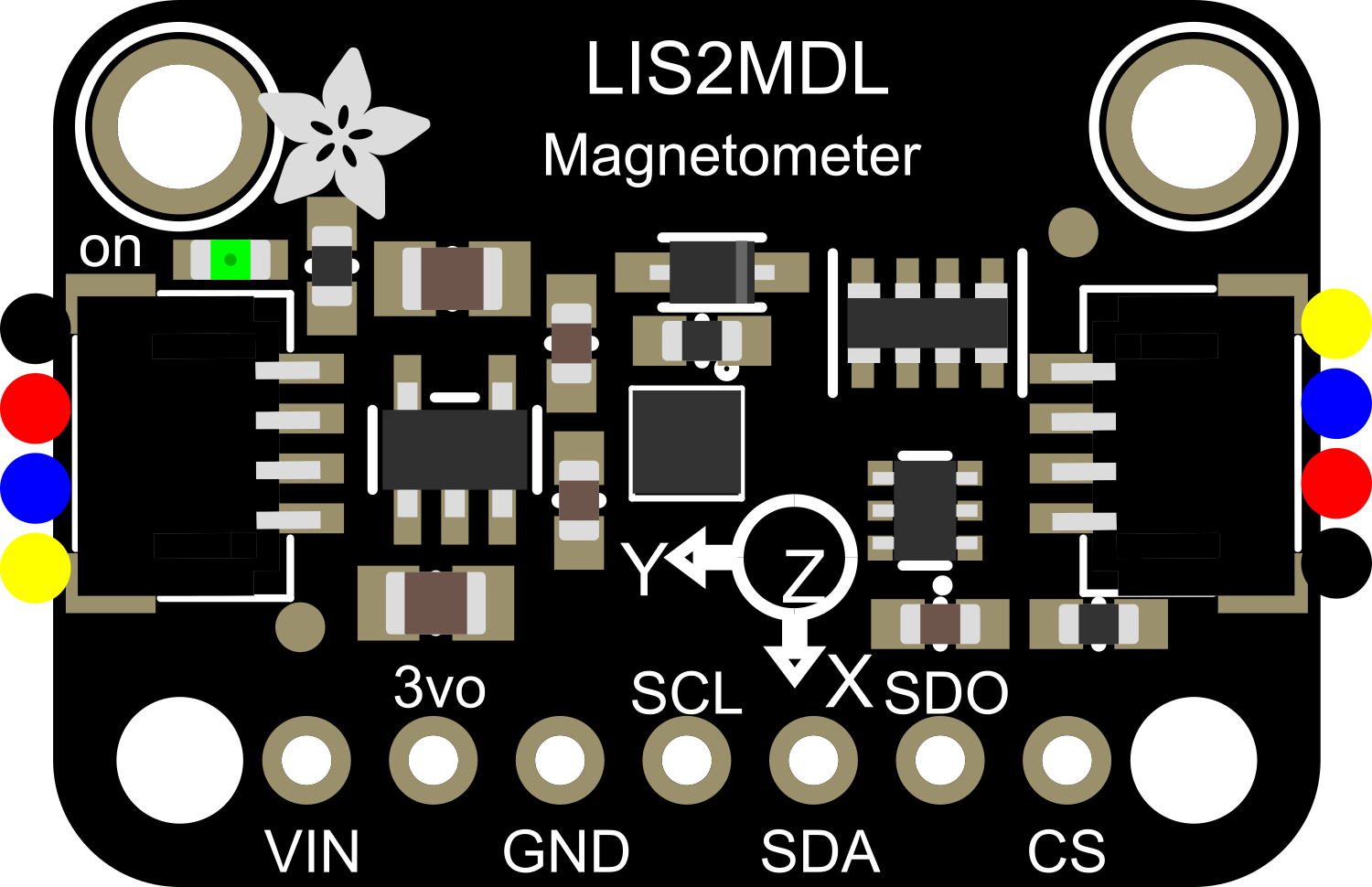
Pin Configuration and Descriptions

Pin Number Name Description
1 VIN Supply voltage (2.5V to 5.5V)
2 GND Ground
3 SDA I2C Data / SPI Serial Data In (SDI)
4 SCL I2C Clock / SPI Serial Clock (SCK)
5 SDO SPI Serial Data Out (optional for I2C)
6 CS SPI Chip Select (active low, optional for I2C)

Usage Instructions

Integration into a Circuit

To use the Adafruit LIS2MDL magnetometer with an Arduino UNO, follow these steps:

  1. Connect VIN to a 3.3V or 5V output on the Arduino.
  2. Connect GND to a ground pin on the Arduino.
  3. For I2C communication:
    • Connect SDA to the A4 pin (SDA) on the Arduino.
    • Connect SCL to the A5 pin (SCL) on the Arduino.
  4. For SPI communication:
    • Connect SDA to the D11 pin (MOSI) on the Arduino.
    • Connect SCL to the D13 pin (SCK) on the Arduino.
    • Connect SDO to the D12 pin (MISO) on the Arduino.
    • Connect CS to a digital pin (e.g., D10) on the Arduino.

Best Practices

  • Use pull-up resistors on the I2C lines if they are not already present on the breakout board.
  • Ensure that the power supply is stable and within the specified voltage range.
  • When using SPI, ensure that the CS pin is correctly managed to avoid communication conflicts.

Example Code for Arduino UNO

Here is a simple example of how to read data from the LIS2MDL using the Arduino's I2C interface:

#include <Wire.h>

// I2C address for the LIS2MDL
#define LIS2MDL_I2C_ADDRESS 0x1E

void setup() {
  Wire.begin(); // Initialize I2C
  Serial.begin(9600); // Start serial communication at 9600 baud
  // Configure the LIS2MDL (additional configuration may be required)
}

void loop() {
  // Read magnetic field data from the LIS2MDL
  // This is a simplified example; additional code is required for a full implementation
  Wire.beginTransmission(LIS2MDL_I2C_ADDRESS);
  // Request data...
  Wire.endTransmission();
  // Read data...
  
  // Process and print the magnetic field data
  Serial.println("Magnetic field (X, Y, Z): ...");
  
  delay(1000); // Wait for 1 second before reading again
}

Note: This code is a template and requires additional implementation to function correctly. You will need to refer to the LIS2MDL datasheet and possibly use a library specifically designed for the sensor to handle the initialization and data reading processes.

Troubleshooting and FAQs

Common Issues

  • No data or incorrect data readings: Ensure that the connections are secure and that the correct I2C address or SPI settings are being used.
  • Intermittent communication: Check for loose connections and ensure that the pull-up resistors are correctly installed for I2C communication.

FAQs

Q: Can the LIS2MDL be used with a 5V microcontroller like the Arduino UNO? A: Yes, the LIS2MDL can be interfaced with a 5V microcontroller. However, ensure that the I2C lines are level-shifted if necessary.

Q: How can I calibrate the magnetometer? A: Calibration involves collecting data at various orientations and then using these data to compensate for offsets and scale factors. Adafruit provides libraries and examples that can help with the calibration process.

Q: What is the maximum sampling rate of the LIS2MDL? A: The maximum sampling rate depends on the operating mode, but it can go up to 100 Hz in continuous mode.

For further assistance, consult the Adafruit LIS2MDL datasheet and the Adafruit support forums.