How to Use timer base: Examples, Pinouts, and Specs
Introduction
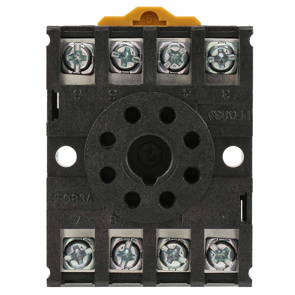
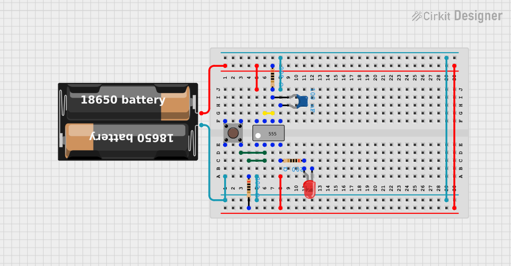
A timer base is a versatile electronic component designed to provide a stable platform for mounting and operating timer circuits. It is commonly used in timing applications to control the duration of events or processes, such as in industrial automation, home appliances, and electronic projects. The timer base ensures reliable operation by offering a secure and organized interface for connecting timer modules and related circuitry.
Explore Projects Built with timer base
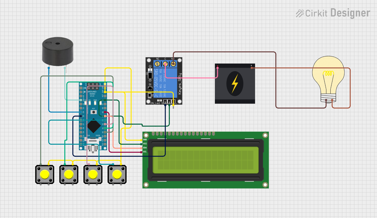
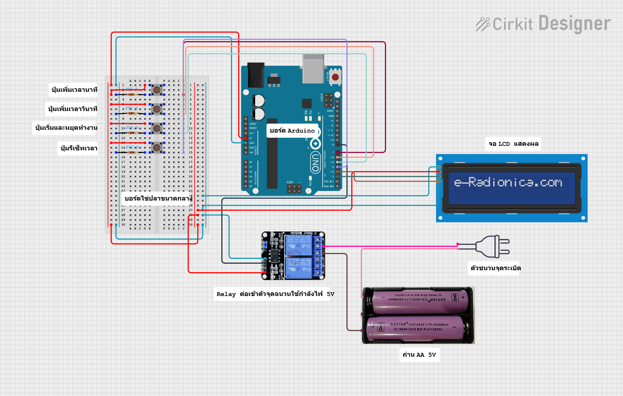
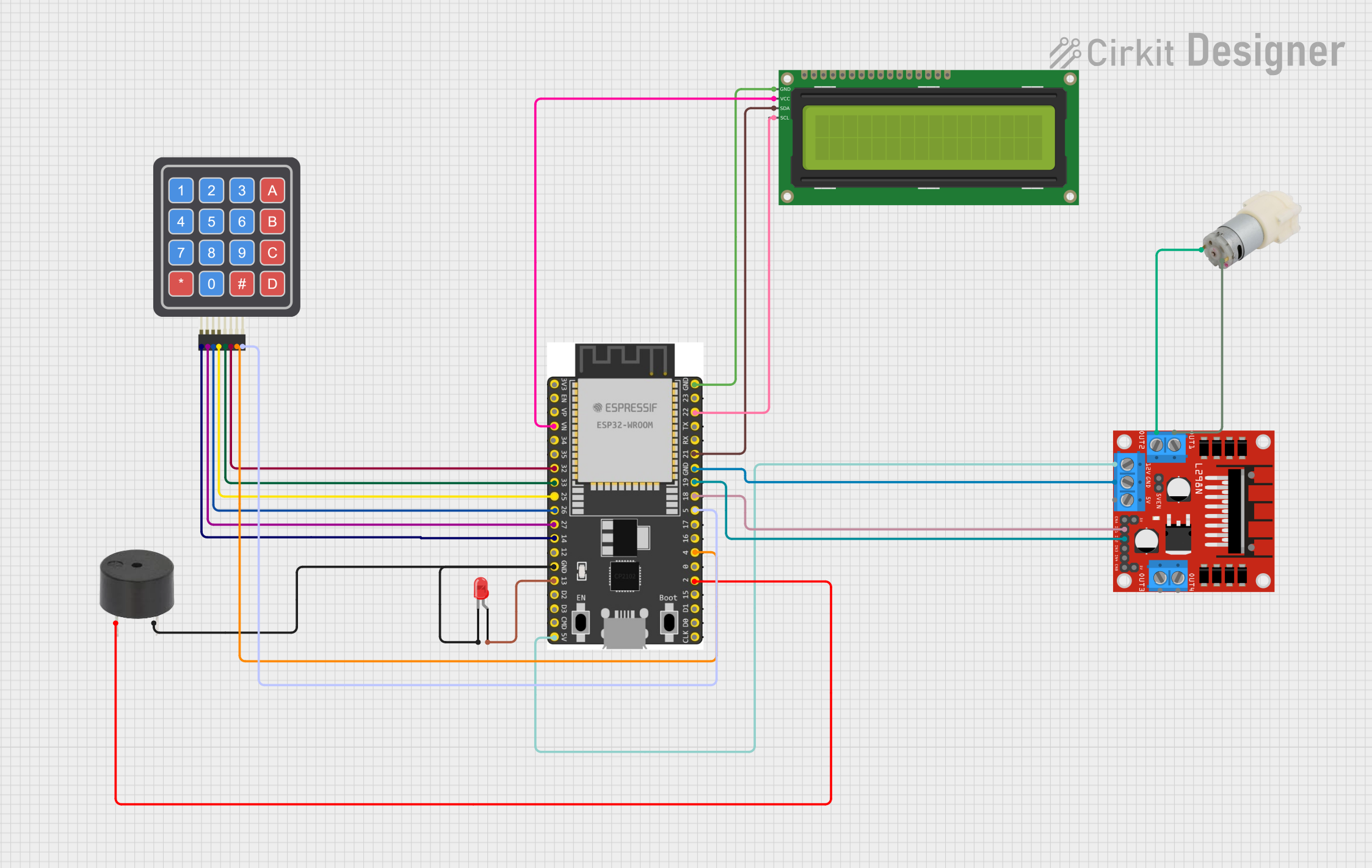
Explore Projects Built with timer base
Common Applications and Use Cases
- Industrial automation systems for process control
- Home appliances like washing machines and microwave ovens
- Timing circuits in DIY electronics projects
- Sequential control in lighting systems
- Delayed switching in motor control applications
Technical Specifications
The timer base itself does not generate timing signals but serves as a foundation for timer circuits. Below are the general specifications and pin configurations for a typical timer base:
Key Technical Details
- Operating Voltage: 5V to 24V DC (depending on the timer module used)
- Current Rating: Up to 10A (varies with the relay or load connected)
- Material: High-quality plastic or metal for durability
- Mounting Type: Screw or DIN rail mount
- Compatibility: Supports a wide range of timer modules (e.g., 555 timer IC, programmable timers)
Pin Configuration and Descriptions
The pin configuration of a timer base depends on the specific timer module it supports. Below is an example configuration for a timer base designed for a 555 timer IC:
| Pin Number | Pin Name | Description |
|---|---|---|
| 1 | GND | Ground connection for the timer circuit. |
| 2 | TRIG | Trigger input to start the timing cycle. |
| 3 | OUT | Output pin that provides the timing signal. |
| 4 | RESET | Resets the timer when pulled low. |
| 5 | CTRL | Control voltage input for adjusting the timing interval (optional). |
| 6 | THR | Threshold input to determine the end of the timing cycle. |
| 7 | DISCH | Discharge pin for the timing capacitor. |
| 8 | VCC | Positive voltage supply for the timer circuit. |
Usage Instructions
How to Use the Timer Base in a Circuit
- Mount the Timer Base: Secure the timer base to a stable surface using screws or a DIN rail, depending on the mounting type.
- Insert the Timer Module: Place the timer module (e.g., 555 timer IC) into the designated socket on the timer base.
- Connect Power Supply: Attach the power supply to the VCC and GND pins, ensuring the voltage matches the timer module's requirements.
- Connect External Components: Add external components like resistors, capacitors, and relays to configure the desired timing interval and output behavior.
- Test the Circuit: Power on the circuit and verify the timing operation using an oscilloscope or multimeter.
Important Considerations and Best Practices
- Check Compatibility: Ensure the timer module is compatible with the timer base before installation.
- Avoid Overloading: Do not exceed the current and voltage ratings of the timer base or connected components.
- Use Proper Wiring: Securely connect all wires to prevent loose connections that could cause malfunction.
- Heat Management: If the timer base is used in high-power applications, ensure adequate ventilation to prevent overheating.
Example: Using a Timer Base with Arduino UNO
The timer base can be used with an Arduino UNO to create a simple timing circuit. Below is an example code snippet to control an LED using a timer base:
// Example: Controlling an LED with a timer base and Arduino UNO

const int timerOutputPin = 7; // Pin connected to the timer base output
const int ledPin = 13;        // Pin connected to the LED

void setup() {
  pinMode(timerOutputPin, INPUT); // Set timer output pin as input
  pinMode(ledPin, OUTPUT);        // Set LED pin as output
}

void loop() {
  int timerState = digitalRead(timerOutputPin); // Read the timer base output

  if (timerState == HIGH) {
    digitalWrite(ledPin, HIGH); // Turn on the LED if timer output is HIGH
  } else {
    digitalWrite(ledPin, LOW);  // Turn off the LED if timer output is LOW
  }
}
Troubleshooting and FAQs
Common Issues and Solutions
Timer Module Not Working:
- Cause: Incorrect power supply or loose connections.
- Solution: Verify the power supply voltage and ensure all connections are secure.
Inconsistent Timing:
- Cause: Faulty or incorrectly connected external components (e.g., resistors, capacitors).
- Solution: Check the values and connections of external components and replace if necessary.
Overheating:
- Cause: Excessive current draw or poor ventilation.
- Solution: Reduce the load on the timer base or improve ventilation around the circuit.
No Output Signal:
- Cause: Timer module not properly seated in the socket.
- Solution: Reinsert the timer module and ensure it is firmly seated.
FAQs
Q: Can I use any timer module with a timer base?
A: No, the timer module must be compatible with the pin configuration and voltage rating of the timer base.
Q: How do I adjust the timing interval?
A: The timing interval can be adjusted by changing the values of the external resistor and capacitor connected to the timer module.
Q: Is the timer base suitable for high-power applications?
A: Timer bases are typically designed for low to moderate power applications. For high-power use, ensure the base and components can handle the required current and voltage.
Q: Can I use a timer base without a microcontroller?
A: Yes, a timer base can operate independently with a timer module and external components to create standalone timing circuits.