How to Use Power Module 5V to 200V: Examples, Pinouts, and Specs
Introduction
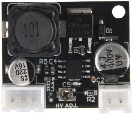
The Power Module 5V to 200V is an electronic component designed to step up a low voltage input to a high voltage output. This module is commonly used in applications requiring high voltage levels from a low voltage power supply, such as powering specialized sensors, Nixie tube displays, or for scientific experiments where high voltage is necessary.
Explore Projects Built with Power Module 5V to 200V


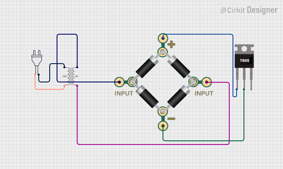
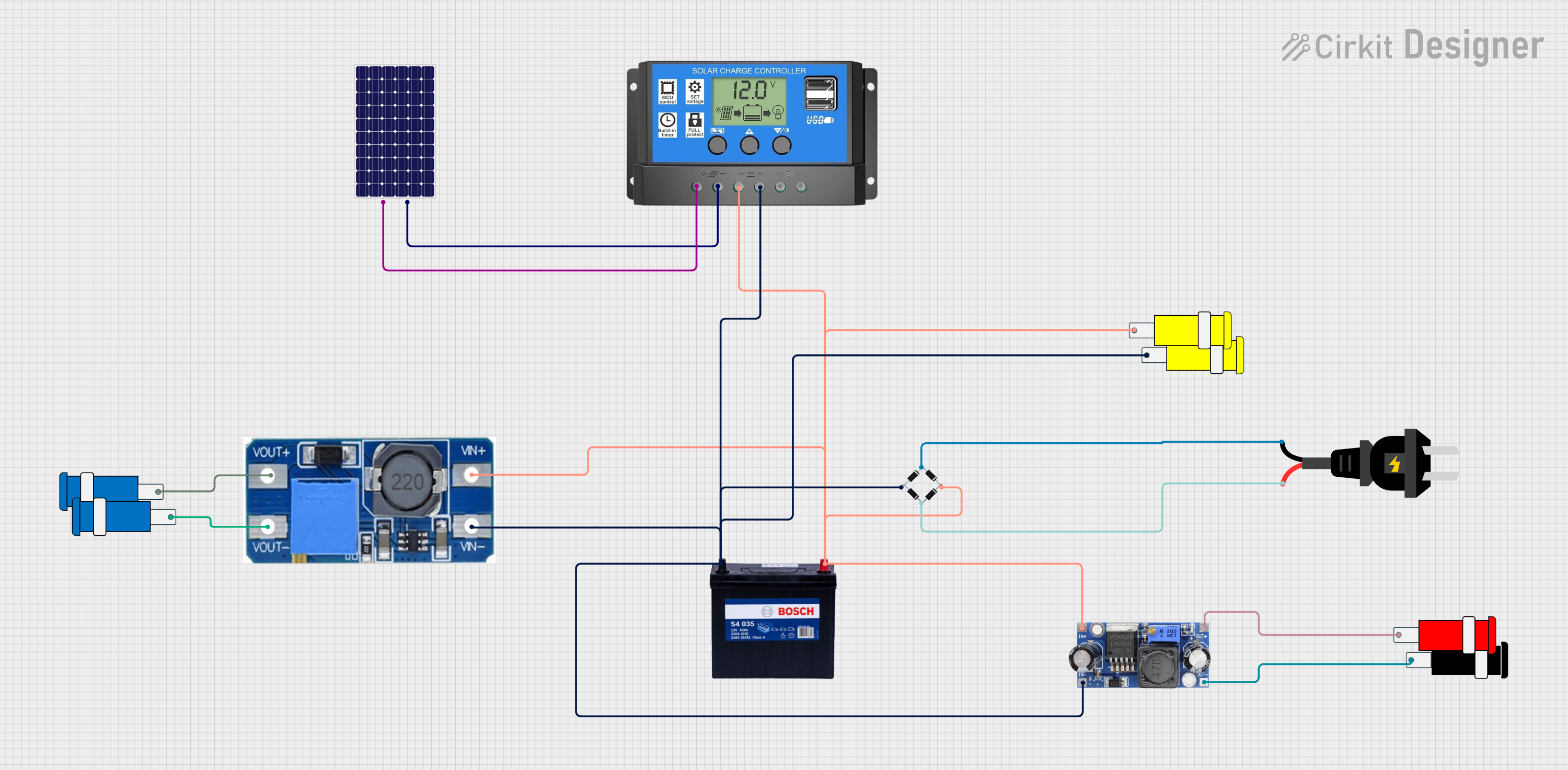
Explore Projects Built with Power Module 5V to 200V
Common Applications and Use Cases:
- Driving Nixie tubes or VFD displays
- High voltage experiments in laboratories
- Powering Geiger counters
- Supplying power to photomultiplier tubes
Technical Specifications
Key Technical Details:
- Input Voltage: 5V DC
- Output Voltage: Adjustable up to 200V DC
- Maximum Output Current: Typically 10mA (depends on input power and voltage)
- Efficiency: Up to 90% (varies with load and input voltage)
- Operating Temperature: -40°C to +85°C
Pin Configuration and Descriptions:
| Pin Number | Description | Notes |
|---|---|---|
| 1 | V_IN | Connect to 5V power supply |
| 2 | GND | Ground |
| 3 | V_OUT | High voltage output up to 200V |
| 4 | Feedback (FB) | Feedback pin for voltage adjust |
| 5 | Enable (EN) | Enable pin for module control |
Usage Instructions
How to Use the Component in a Circuit:
Power Supply Connection:
- Connect the 5V power supply to the V_IN and GND pins of the module.
Output Connection:
- Connect the load to the V_OUT and GND pins. Ensure that the load can handle the high voltage output.
Voltage Adjustment:
- Adjust the output voltage by varying the voltage on the Feedback (FB) pin. This can be done using a potentiometer or a voltage divider circuit.
Enabling the Module:
- The module can be enabled or disabled via the Enable (EN) pin. Applying a high signal (close to V_IN) will enable the module, while a low signal (close to GND) will disable it.
Important Considerations and Best Practices:
Heat Dissipation:
- Ensure adequate heat sinking for the module, as high voltage conversion can generate significant heat.
Safety Precautions:
- High voltages are dangerous. Take appropriate safety measures to prevent electric shock.
Load Capacitance:
- Be mindful of the capacitive load the module can handle. Excessive capacitance may affect performance or damage the module.
Input Voltage:
- Do not exceed the recommended input voltage as it may damage the module.
Troubleshooting and FAQs
Common Issues Users Might Face:
Insufficient Output Voltage:
- Check if the input voltage is stable and at 5V.
- Verify the connections to the Feedback (FB) pin and adjust as necessary.
Module Overheating:
- Ensure the load does not exceed the maximum output current specification.
- Improve heat dissipation with a heat sink or by improving airflow.
Module Not Powering On:
- Check the connection to the Enable (EN) pin and ensure it is receiving the correct signal.
Solutions and Tips for Troubleshooting:
Output Voltage Calibration:
- Use a multimeter to measure the output voltage while adjusting the Feedback (FB) pin to calibrate the voltage accurately.
Safety First:
- Always discharge capacitors and remove power before making adjustments to the circuit.
FAQs:
Q: Can I use this module to power a microcontroller? A: No, this module outputs high voltage which is not suitable for low voltage electronics like microcontrollers.
Q: Is it possible to control the output voltage digitally? A: Yes, you can use a digital-to-analog converter (DAC) or a PWM signal filtered to an analog voltage to control the Feedback (FB) pin.
Q: What is the maximum load this module can drive? A: The maximum load is determined by the maximum output current, which is typically 10mA. Ensure the load does not exceed this rating.
Q: How can I ensure the longevity of the module? A: Avoid running the module at its maximum ratings continuously, provide adequate cooling, and ensure the input voltage is stable.
Note: This documentation assumes a generic power module and may not cover all specific details or variations of actual modules. Always consult the datasheet of the specific module you are using for precise information.