How to Use Tactile Switch Buttons - 12mm Square: Examples, Pinouts, and Specs
Introduction
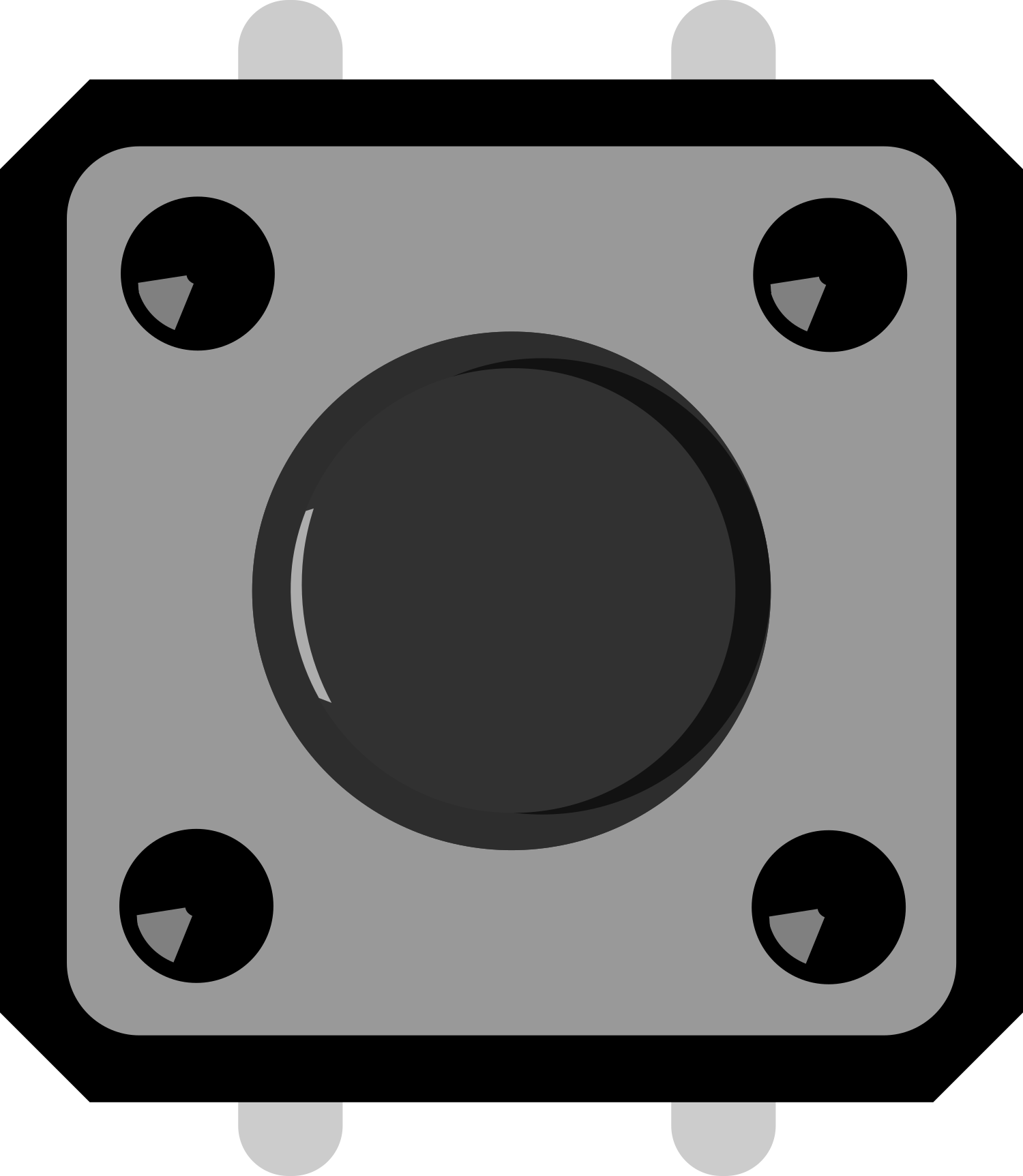
Tactile Switch Buttons are a fundamental component in electronic design, providing a simple and effective way to input user commands. These switches are known for their tactile feedback, which gives a noticeable click when the button is pressed, reassuring the user of the action. With a compact and versatile 12mm square form factor, these buttons are widely used in various applications, including consumer electronics, control panels, and hobbyist projects with microcontrollers like Arduino.
Explore Projects Built with Tactile Switch Buttons - 12mm Square
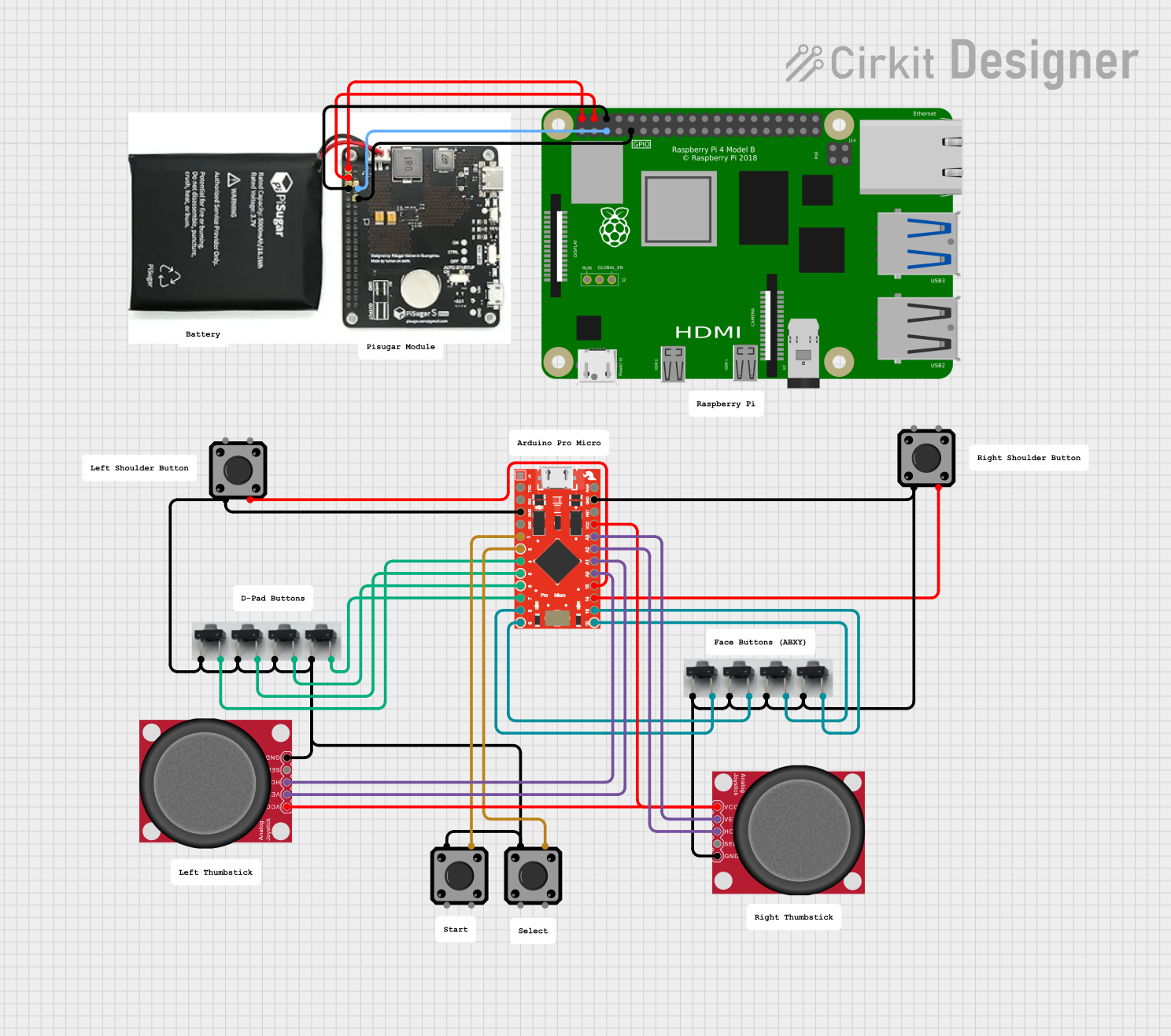
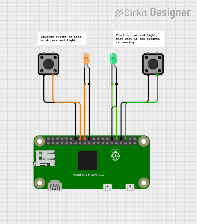
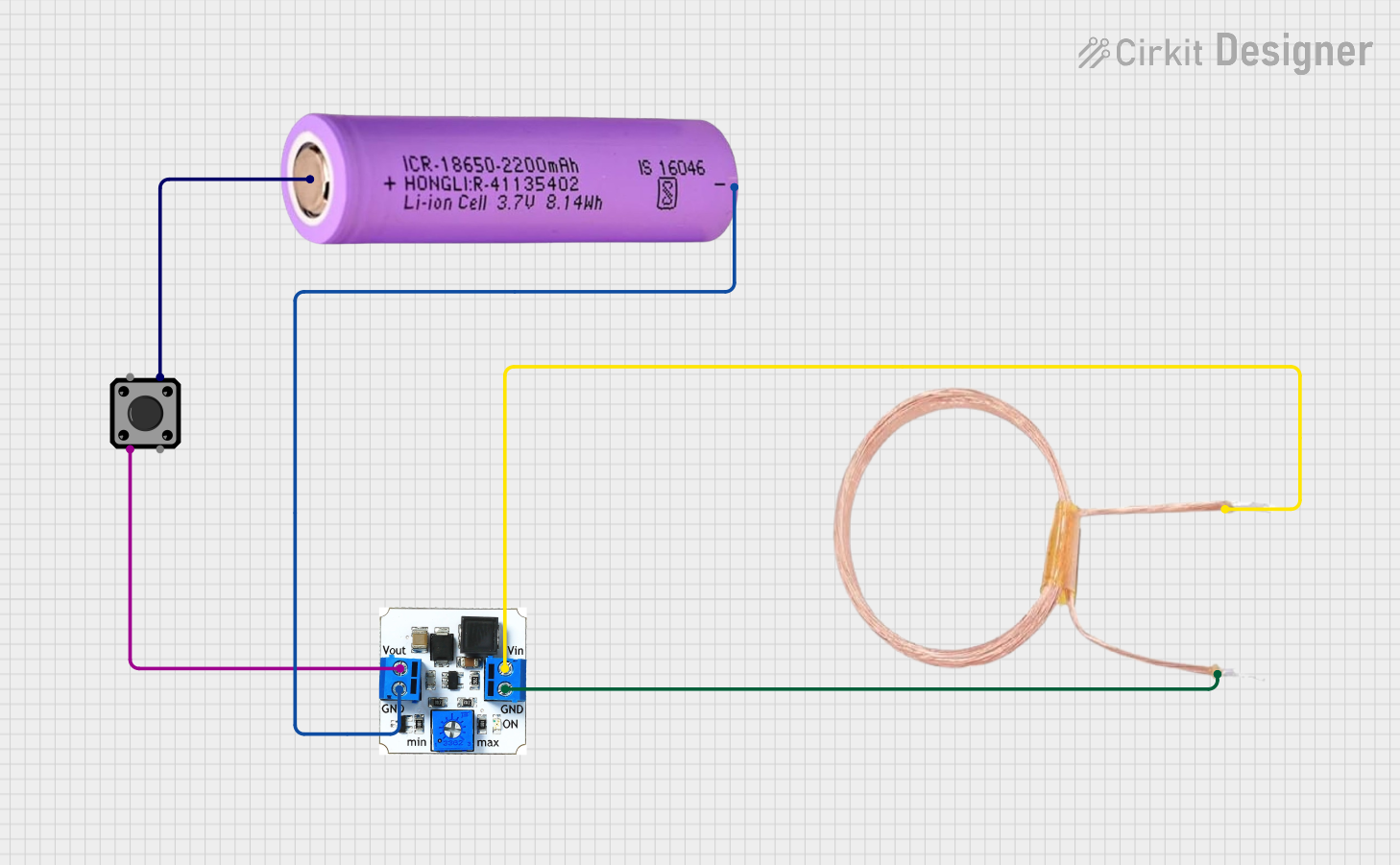
Explore Projects Built with Tactile Switch Buttons - 12mm Square
Technical Specifications
General Characteristics
- Switch Type: Momentary tactile switch
- Dimensions: 12mm x 12mm x 4.3mm (Height may vary)
- Actuation Force: Typically around 50g to 300g
- Life Cycle: Typically 100,000 to 1,000,000 cycles
- Operating Temperature: -20°C to 70°C
Electrical Specifications
- Contact Rating: 50mA @ 12V DC (maximum)
- Contact Resistance: ≤ 100mΩ initial
- Insulation Resistance: ≥ 100MΩ at 100V DC
- Dielectric Strength: 250V AC for 1 min
Pin Configuration and Descriptions
| Pin Number | Description |
|---|---|
| 1 | Normally Open (NO) |
| 2 | Common (COM) |
| 3 | Normally Open (NO) |
| 4 | Common (COM) |
Note: Pins 1 and 3 are internally connected, as are pins 2 and 4. This allows for flexibility in the PCB design.
Usage Instructions
Integration into a Circuit
- Mounting: Secure the tactile switch onto the PCB ensuring proper alignment of the pins.
- Wiring: Connect one of the NO pins to the input signal line and one of the COM pins to ground. The other set of NO and COM pins can be left unused or connected in parallel for redundancy.
- Debouncing: Implement a hardware or software debounce mechanism to prevent false triggering due to mechanical bounce.
Best Practices
- Use a pull-up resistor (typically 10kΩ) on the input line to ensure a defined logic level when the switch is open.
- Avoid applying force to the sides of the switch to prevent damage.
- Test the switch functionality before finalizing the circuit design.
Example Code for Arduino UNO
// Define the pin connected to the switch
const int buttonPin = 2;
// Variable for reading the pushbutton status
int buttonState = 0;

void setup() {
  // Initialize the pushbutton pin as an input with an internal pull-up resistor
  pinMode(buttonPin, INPUT_PULLUP);
}

void loop() {
  // Read the state of the pushbutton value
  buttonState = digitalRead(buttonPin);

  // Check if the pushbutton is pressed
  // If it is, the buttonState is LOW
  if (buttonState == LOW) {
    // Turn on the LED (in this example, the built-in LED on pin 13)
    digitalWrite(13, HIGH);
  } else {
    // Turn off the LED
    digitalWrite(13, LOW);
  }
}
Note: The code assumes the use of the built-in pull-up resistor feature of the Arduino UNO. The switch is connected to pin 2 and ground.
Troubleshooting and FAQs
Common Issues
- Switch does not respond: Ensure the switch is properly soldered and there are no cold solder joints.
- Intermittent operation: Check for mechanical damage or wear if the switch has been used extensively.
- Bouncing signals: Implement a debounce algorithm in software or use a hardware debounce circuit.
FAQs
Q: Can I use these switches with higher voltages? A: No, these switches are rated for a maximum of 50mA at 12V DC. Applying higher voltages can damage the switch.
Q: How can I tell if the switch is working during prototyping? A: You can use a multimeter to check for continuity between the NO and COM pins when the switch is pressed.
Q: Are these switches waterproof? A: No, standard tactile switches are not waterproof. Specialized switches should be used for applications requiring water resistance.
For further assistance, consult the manufacturer's datasheet or contact technical support.