Cirkit Designer Logo
Cirkit Designer
Your all-in-one circuit design IDE
Home / 
Component Documentation

How to Use IP2326 2S LX LSCV2: Examples, Pinouts, and Specs

Image of  IP2326 2S LX LSCV2
Cirkit Designer LogoDesign with IP2326 2S LX LSCV2 in Cirkit Designer

Introduction

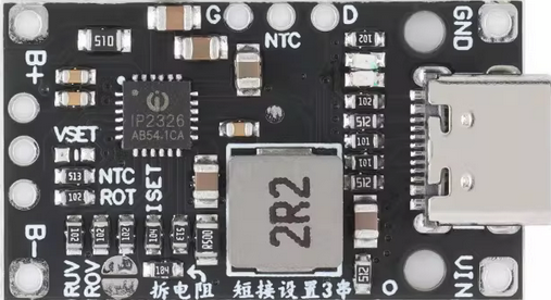
The IP2326 2S LX LSCV2 is a highly efficient lithium-ion battery protection integrated circuit (IC) designed for 2-cell (2S) battery packs. It provides overcharge, over-discharge, overcurrent, and short-circuit protection, ensuring the safety and longevity of lithium-ion batteries. This IC is commonly used in battery management systems (BMS) for portable electronics, power tools, and other rechargeable devices.

Explore Projects Built with IP2326 2S LX LSCV2

Use Cirkit Designer to design, explore, and prototype these projects online. Some projects support real-time simulation. Click "Open Project" to start designing instantly!
ESP32-Based Portable Smart Speaker with Audio Input Processing
Image of talkAI: A project utilizing  IP2326 2S LX LSCV2 in a practical application
This circuit features two ESP32 microcontrollers configured for serial communication, with one ESP32's TX0 connected to the other's RX2, and vice versa. An INMP441 microphone is interfaced with one ESP32 for audio input, using I2S protocol with connections for serial clock (SCK), word select (WS), and serial data (SD). A Max98357 audio amplifier is connected to the other ESP32 to drive a loudspeaker, receiving I2S data (DIN), bit clock (BLCK), and left-right clock (LRC), and is powered by a lipo battery charger module.
Cirkit Designer LogoOpen Project in Cirkit Designer
Cellular-Enabled IoT Device with Real-Time Clock and Power Management
Image of LRCM PHASE 2 BASIC: A project utilizing  IP2326 2S LX LSCV2 in a practical application
This circuit features a LilyGo-SIM7000G module for cellular communication and GPS functionality, interfaced with an RTC DS3231 for real-time clock capabilities. It includes voltage sensing through two voltage sensor modules, and uses an 8-channel opto-coupler for isolating different parts of the circuit. Power management is handled by a buck converter connected to a DC power source and batteries, with a fuse for protection and a rocker switch for on/off control. Additionally, there's an LED for indication purposes.
Cirkit Designer LogoOpen Project in Cirkit Designer
ESP32-Controlled Multi-Axis Actuator System with Orientation Sensing and Light Detection
Image of Auto_Level_Table: A project utilizing  IP2326 2S LX LSCV2 in a practical application
This circuit features an ESP32 S3 N32R8V microcontroller interfaced with multiple IBT-2 H-Bridge Motor Drivers to control several Linear Actuators, and it receives input from KY-018 LDR Photo Resistors and Pushbuttons. The ESP32 is powered by a 5V supply from an Adafruit MPM3610 5V Buck Converter, while the Linear Actuators and Motor Drivers are powered by a 12V 7Ah battery. Additionally, the ESP32 communicates with an Adafruit BNO085 9-DOF Orientation IMU Fusion Breakout for orientation sensing.
Cirkit Designer LogoOpen Project in Cirkit Designer
ESP8266 and SIM800L Based GPS Tracker with I2C LCD Display and Battery Power
Image of Little Innovator Competition: A project utilizing  IP2326 2S LX LSCV2 in a practical application
This circuit integrates an ESP8266 NodeMCU microcontroller with a SIM800L GSM module, a GPS NEO 6M module, and a 16x2 I2C LCD display for communication and location tracking. It also includes a pushbutton for user input, a piezo buzzer for audio alerts, and is powered by a 2x 18650 battery pack through an LM2596 step-down module.
Cirkit Designer LogoOpen Project in Cirkit Designer

Explore Projects Built with IP2326 2S LX LSCV2

Use Cirkit Designer to design, explore, and prototype these projects online. Some projects support real-time simulation. Click "Open Project" to start designing instantly!
Image of talkAI: A project utilizing  IP2326 2S LX LSCV2 in a practical application
ESP32-Based Portable Smart Speaker with Audio Input Processing
This circuit features two ESP32 microcontrollers configured for serial communication, with one ESP32's TX0 connected to the other's RX2, and vice versa. An INMP441 microphone is interfaced with one ESP32 for audio input, using I2S protocol with connections for serial clock (SCK), word select (WS), and serial data (SD). A Max98357 audio amplifier is connected to the other ESP32 to drive a loudspeaker, receiving I2S data (DIN), bit clock (BLCK), and left-right clock (LRC), and is powered by a lipo battery charger module.
Cirkit Designer LogoOpen Project in Cirkit Designer
Image of LRCM PHASE 2 BASIC: A project utilizing  IP2326 2S LX LSCV2 in a practical application
Cellular-Enabled IoT Device with Real-Time Clock and Power Management
This circuit features a LilyGo-SIM7000G module for cellular communication and GPS functionality, interfaced with an RTC DS3231 for real-time clock capabilities. It includes voltage sensing through two voltage sensor modules, and uses an 8-channel opto-coupler for isolating different parts of the circuit. Power management is handled by a buck converter connected to a DC power source and batteries, with a fuse for protection and a rocker switch for on/off control. Additionally, there's an LED for indication purposes.
Cirkit Designer LogoOpen Project in Cirkit Designer
Image of Auto_Level_Table: A project utilizing  IP2326 2S LX LSCV2 in a practical application
ESP32-Controlled Multi-Axis Actuator System with Orientation Sensing and Light Detection
This circuit features an ESP32 S3 N32R8V microcontroller interfaced with multiple IBT-2 H-Bridge Motor Drivers to control several Linear Actuators, and it receives input from KY-018 LDR Photo Resistors and Pushbuttons. The ESP32 is powered by a 5V supply from an Adafruit MPM3610 5V Buck Converter, while the Linear Actuators and Motor Drivers are powered by a 12V 7Ah battery. Additionally, the ESP32 communicates with an Adafruit BNO085 9-DOF Orientation IMU Fusion Breakout for orientation sensing.
Cirkit Designer LogoOpen Project in Cirkit Designer
Image of Little Innovator Competition: A project utilizing  IP2326 2S LX LSCV2 in a practical application
ESP8266 and SIM800L Based GPS Tracker with I2C LCD Display and Battery Power
This circuit integrates an ESP8266 NodeMCU microcontroller with a SIM800L GSM module, a GPS NEO 6M module, and a 16x2 I2C LCD display for communication and location tracking. It also includes a pushbutton for user input, a piezo buzzer for audio alerts, and is powered by a 2x 18650 battery pack through an LM2596 step-down module.
Cirkit Designer LogoOpen Project in Cirkit Designer

Common Applications and Use Cases

  • Lithium-ion battery packs for consumer electronics
  • Power tools and cordless devices
  • Electric bicycles and scooters
  • Backup power systems and uninterruptible power supplies (UPS)

Technical Specifications

Key Technical Details

  • Operating Voltage Range: 4.25V to 8.4V (2-cell configuration)
  • Overcharge Detection Voltage: 4.25V ± 0.025V per cell
  • Over-discharge Detection Voltage: 2.50V ± 0.08V per cell
  • Overcurrent Protection: 3A to 6A (configurable via external components)
  • Short-Circuit Protection: Triggered at high current spikes
  • Quiescent Current: ≤ 10µA
  • Operating Temperature Range: -40°C to +85°C
  • Package Type: SOT-23-6

Pin Configuration and Descriptions

The IP2326 2S LX LSCV2 comes in a 6-pin SOT-23 package. Below is the pinout and description:

Pin Number Pin Name Description
1 VDD Positive power supply input; connects to the positive terminal of the battery.
2 COUT Overcharge detection output; controls the external MOSFET for charge protection.
3 DOUT Over-discharge detection output; controls the external MOSFET for discharge protection.
4 VSS Ground connection; connects to the negative terminal of the battery.
5 VM Voltage monitoring input for the second cell in the 2S configuration.
6 V1 Voltage monitoring input for the first cell in the 2S configuration.

Usage Instructions

How to Use the Component in a Circuit

  1. Connect the Battery Pack:

    • Connect the positive terminal of the battery pack to the VDD pin.
    • Connect the negative terminal of the battery pack to the VSS pin.
    • Connect the midpoint between the two cells to the VM pin for voltage monitoring.
  2. External MOSFETs:

    • Use N-channel MOSFETs for charge and discharge control.
    • Connect the gates of the MOSFETs to the COUT and DOUT pins, respectively.
  3. Load and Charger Connections:

    • Connect the load to the discharge MOSFET's drain.
    • Connect the charger to the charge MOSFET's drain.
  4. Resistors and Capacitors:

    • Add appropriate resistors and capacitors as specified in the datasheet to stabilize the circuit and configure overcurrent protection.

Important Considerations and Best Practices

  • Ensure the battery pack is properly balanced before connecting to the IC.
  • Use low-resistance MOSFETs to minimize power loss and heat generation.
  • Avoid exceeding the IC's voltage and current ratings to prevent damage.
  • Place decoupling capacitors close to the IC to reduce noise and improve stability.

Example Code for Arduino UNO

The IP2326 2S LX LSCV2 does not directly interface with microcontrollers like the Arduino UNO. However, you can monitor the battery pack's voltage using the Arduino's analog input pins. Below is an example code snippet to monitor the voltage of a 2S battery pack:

// Define analog input pins for voltage monitoring
const int cell1Pin = A0; // Connect to the midpoint (VM pin)
const int cell2Pin = A1; // Connect to the positive terminal (VDD pin)

// Define voltage divider resistors (adjust based on your circuit)
const float R1 = 10000.0; // Resistor connected to the battery
const float R2 = 10000.0; // Resistor connected to ground

// ADC reference voltage
const float VREF = 5.0; // Arduino UNO's default reference voltage

void setup() {
  Serial.begin(9600); // Initialize serial communication
}

void loop() {
  // Read analog values
  int cell1ADC = analogRead(cell1Pin);
  int cell2ADC = analogRead(cell2Pin);

  // Convert ADC values to voltages
  float cell1Voltage = (cell1ADC * VREF / 1023.0) * ((R1 + R2) / R2);
  float cell2Voltage = (cell2ADC * VREF / 1023.0) * ((R1 + R2) / R2);

  // Calculate total battery voltage
  float totalVoltage = cell1Voltage + cell2Voltage;

  // Print voltages to the Serial Monitor
  Serial.print("Cell 1 Voltage: ");
  Serial.print(cell1Voltage);
  Serial.println(" V");

  Serial.print("Cell 2 Voltage: ");
  Serial.print(cell2Voltage);
  Serial.println(" V");

  Serial.print("Total Battery Voltage: ");
  Serial.print(totalVoltage);
  Serial.println(" V");

  delay(1000); // Wait for 1 second before the next reading
}

Troubleshooting and FAQs

Common Issues Users Might Face

  1. The IC does not trigger overcharge or over-discharge protection.

    • Solution: Verify that the battery voltage levels are within the IC's detection thresholds. Check the connections to the VM and V1 pins.
  2. Excessive heat generation in the MOSFETs.

    • Solution: Use MOSFETs with lower Rds(on) values to reduce power dissipation. Ensure proper heat sinking if necessary.
  3. The circuit does not power the load or charge the battery.

    • Solution: Check the connections to the COUT and DOUT pins. Ensure the MOSFETs are functioning correctly.
  4. The IC consumes too much current.

    • Solution: Verify that there are no short circuits or incorrect connections. Ensure the quiescent current is within the specified range.

Tips for Troubleshooting

  • Use a multimeter to measure voltages at key points in the circuit.
  • Double-check the pin connections and ensure they match the pinout table.
  • Refer to the IC's datasheet for detailed application notes and example circuits.