
How to Use TPS6211*: Examples, Pinouts, and Specs
 Design with TPS6211* in Cirkit Designer
Introduction
The TPS62112 is a high-efficiency step-down DC-DC converter manufactured by Texas Instruments. It is designed for portable and battery-powered applications, offering a compact solution for converting a wide range of input voltages into a stable, adjustable output voltage. With its low quiescent current and integrated features such as power good indication and thermal shutdown, the TPS62112 ensures reliable and efficient operation in various electronic systems.
Explore Projects Built with TPS6211*
 Open Project in Cirkit Designer
 Open Project in Cirkit Designer
 Open Project in Cirkit Designer
 Open Project in Cirkit Designer
Explore Projects Built with TPS6211*
Open Project in Cirkit DesignerOpen Project in Cirkit DesignerOpen Project in Cirkit DesignerOpen Project in Cirkit DesignerCommon Applications
- Battery-powered devices (e.g., smartphones, tablets, and wearables)
- Industrial and medical equipment
- Point-of-load power supplies
- Portable instrumentation
- Embedded systems requiring efficient voltage regulation
Technical Specifications
Key Technical Details
| Parameter | Value |
|---|---|
| Input Voltage Range | 3.1 V to 17 V |
| Output Voltage Range | Adjustable from 0.9 V to 6 V |
| Output Current | Up to 1.5 A |
| Efficiency | Up to 95% |
| Quiescent Current | 22 µA (typical) |
| Switching Frequency | 1 MHz |
| Operating Temperature Range | -40°C to +85°C |
| Package Type | 16-pin TSSOP |
Pin Configuration and Descriptions
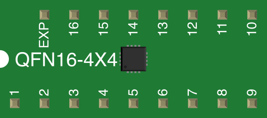
The TPS62112 is available in a 16-pin TSSOP package. Below is the pinout and description:
| Pin Number | Pin Name | Description |
|---|---|---|
| 1 | EN | Enable pin. High to enable the device. |
| 2 | PG | Power Good output. Indicates output status. |
| 3 | FB | Feedback pin for output voltage adjustment. |
| 4 | GND | Ground connection. |
| 5 | VIN | Input voltage supply. |
| 6 | SW | Switch node. Connect to the inductor. |
| 7 | VOUT | Regulated output voltage. |
| 8 | COMP | Compensation pin for stability adjustment. |
| 9-16 | NC | No connection. Leave unconnected. |
Usage Instructions
How to Use the TPS62112 in a Circuit
- Input Voltage Supply: Connect the input voltage (3.1 V to 17 V) to the VIN pin. Use a decoupling capacitor (e.g., 10 µF) close to the VIN pin to reduce noise.
- Output Voltage Adjustment: Use a resistor divider network connected to the FB pin to set the desired output voltage. Refer to the formula in the datasheet for calculating resistor values.
- Inductor Selection: Choose an inductor with appropriate current rating and inductance value (e.g., 10 µH) to ensure stable operation.
- Enable Pin: Drive the EN pin high to enable the device. Pull it low to disable the output.
- Power Good Monitoring: Use the PG pin to monitor the output voltage status. A high signal indicates the output is within regulation.
- Thermal Considerations: Ensure proper PCB layout with adequate thermal dissipation to prevent overheating.
Example Circuit
Below is a basic circuit diagram for using the TPS62112:
VIN (3.1V-17V) ----[10µF]---- VIN
                          |
                          |
                         SW ----[Inductor]---- VOUT
                          |                   |
                          |                   |
                         GND                 FB ----[Resistor Divider]---- GND
Arduino UNO Example Code
The TPS62112 can be used to power an Arduino UNO or other microcontrollers. Below is an example code snippet to monitor the Power Good (PG) pin:
// Define the PG pin connected to Arduino
const int pgPin = 2; // Connect PG pin of TPS62112 to digital pin 2

void setup() {
  pinMode(pgPin, INPUT); // Set PG pin as input
  Serial.begin(9600);    // Initialize serial communication
}

void loop() {
  int pgStatus = digitalRead(pgPin); // Read the PG pin status

  if (pgStatus == HIGH) {
    Serial.println("TPS62112 Output Voltage is Stable.");
  } else {
    Serial.println("TPS62112 Output Voltage is NOT Stable.");
  }

  delay(1000); // Wait for 1 second before checking again
}
Troubleshooting and FAQs
Common Issues and Solutions
Output Voltage Not Stable:
- Check the resistor divider network connected to the FB pin. Ensure the resistor values are correct for the desired output voltage.
- Verify the inductor and capacitor values. Incorrect values can cause instability.
Device Overheating:
- Ensure proper PCB layout with sufficient thermal vias and copper area for heat dissipation.
- Check if the input voltage or load current exceeds the device's specifications.
Power Good (PG) Pin Not Responding:
- Verify the connection between the PG pin and the monitoring circuit.
- Ensure the output voltage is within the regulation range.
No Output Voltage:
- Confirm that the EN pin is driven high to enable the device.
- Check the input voltage and ensure it is within the specified range.
FAQs
Q1: Can the TPS62112 operate with a fixed output voltage?
A1: No, the TPS62112 requires an external resistor divider network to set the output voltage. It does not have fixed output voltage options.
Q2: What is the maximum load current supported?
A2: The TPS62112 can supply up to 1.5 A of continuous output current.
Q3: How do I calculate the resistor values for the FB pin?
A3: Use the formula provided in the datasheet:
[ V_{OUT} = V_{REF} \times \left(1 + \frac{R1}{R2}\right) ]
Where ( V_{REF} ) is 0.9 V, and ( R1 ) and ( R2 ) are the feedback resistors.
Q4: Can I use the TPS62112 for 12 V to 5 V conversion?
A4: Yes, the TPS62112 supports input voltages up to 17 V and can step down to 5 V with appropriate external components.
This concludes the documentation for the TPS62112. For further details, refer to the official datasheet provided by Texas Instruments.