How to Use Servo: Examples, Pinouts, and Specs
Introduction
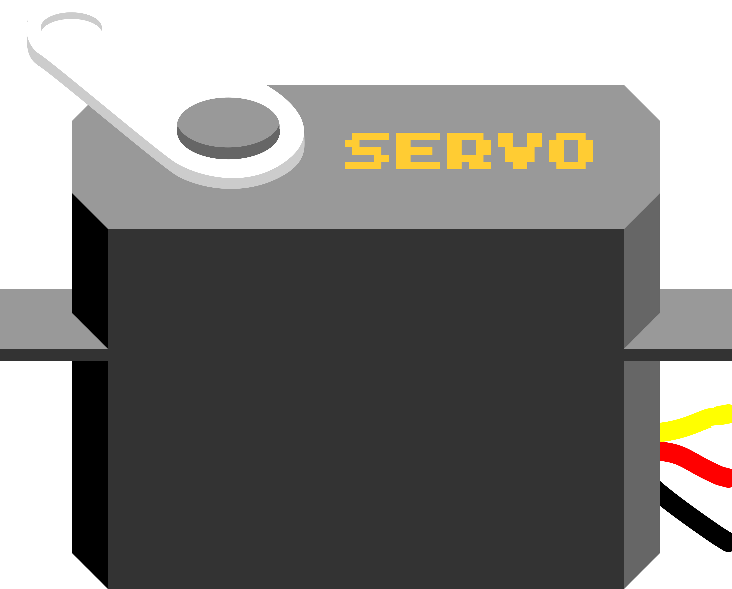
A servo is a rotary actuator that allows for precise control of angular position, velocity, and acceleration. It consists of a motor coupled to a sensor for position feedback, along with a control circuit. Servos are widely used in robotics, automation, remote-controlled vehicles, and industrial machinery due to their ability to provide accurate and repeatable motion.
Explore Projects Built with Servo

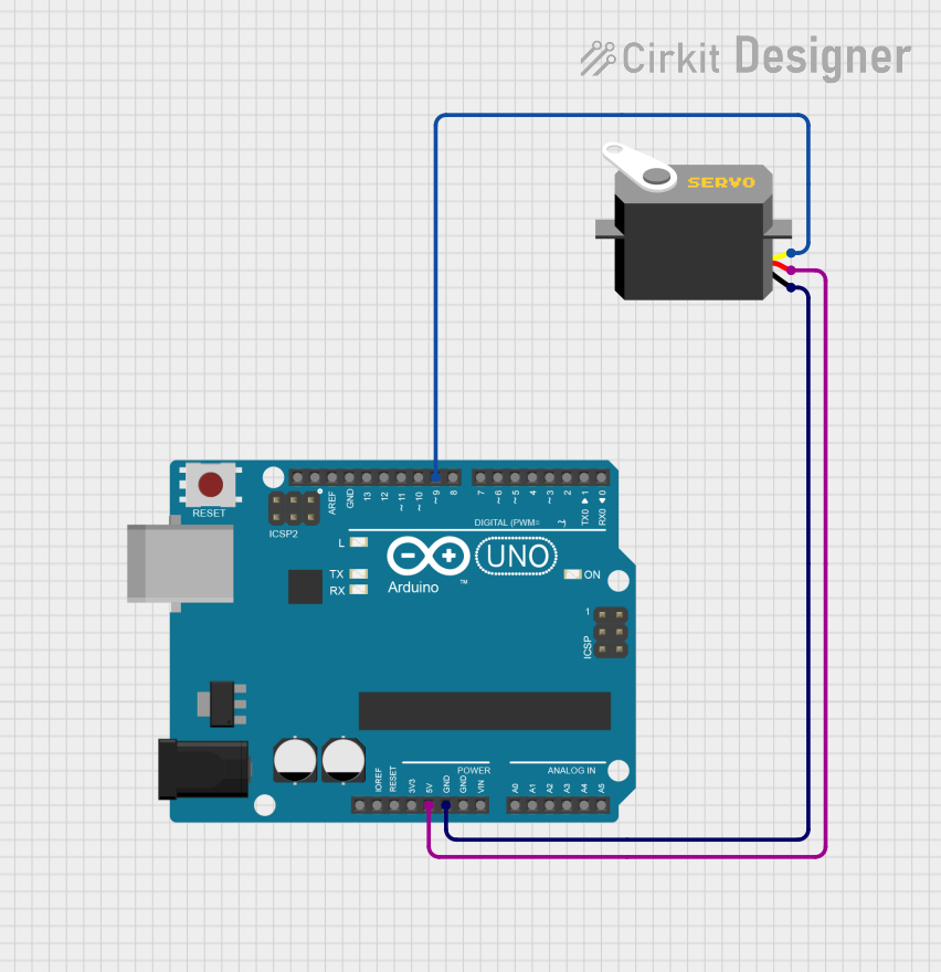
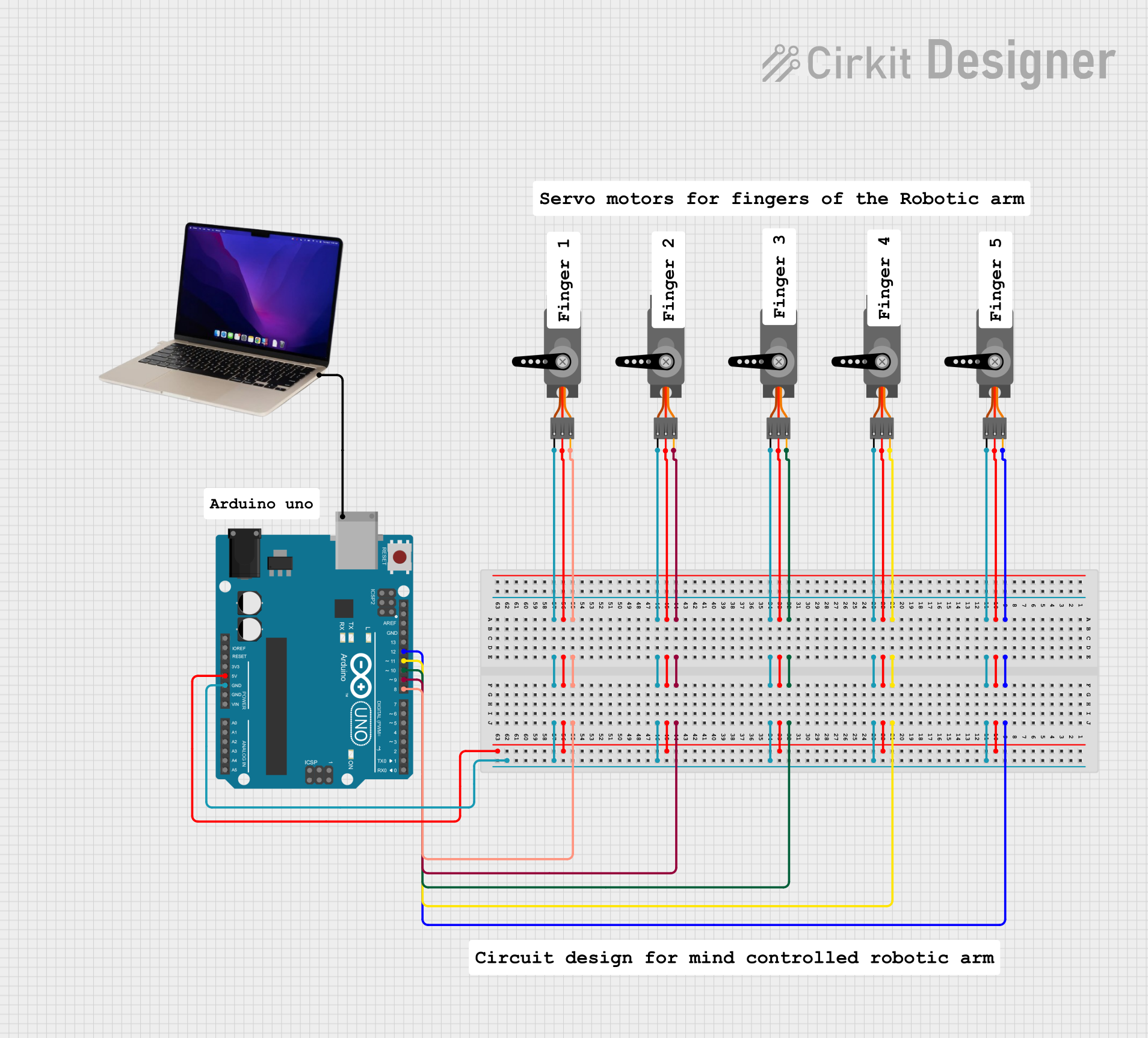
Explore Projects Built with Servo
Common Applications and Use Cases
- Robotics: For controlling robotic arms, grippers, and joints.
- Remote-controlled vehicles: Steering mechanisms and throttle control.
- Automation: Conveyor systems and precise positioning tasks.
- Hobby projects: Model airplanes, boats, and cars.
- Camera gimbals: Stabilization and precise movement.
Technical Specifications
Below are the general technical specifications for a standard hobby servo. Note that specifications may vary depending on the specific model and manufacturer.
Key Technical Details
- Operating Voltage: 4.8V to 6V (typical range)
- Current Draw: 10mA to 100mA (idle), up to 1A (under load)
- Torque: 1.5 kg-cm to 20 kg-cm (varies by model)
- Rotation Range: 0° to 180° (standard), 360° for continuous rotation servos
- Control Signal: Pulse Width Modulation (PWM)
- Pulse width: 1ms (0°), 1.5ms (90°), 2ms (180°)
- Frequency: 50Hz (20ms period)
Pin Configuration and Descriptions
The servo typically has three wires for connection:
| Pin Name | Wire Color (Common) | Description |
|---|---|---|
| VCC | Red | Power supply (4.8V to 6V) |
| GND | Black/Brown | Ground |
| Signal | Yellow/Orange/White | PWM control signal |
Usage Instructions
How to Use the Servo in a Circuit
- Power the Servo: Connect the VCC pin to a 5V or 6V power source and the GND pin to the ground of the circuit.
- Control Signal: Connect the Signal pin to a PWM-capable pin of a microcontroller (e.g., Arduino).
- PWM Signal: Generate a PWM signal with a frequency of 50Hz and adjust the pulse width to control the servo's position:
- 1ms pulse: 0° position
- 1.5ms pulse: 90° position
- 2ms pulse: 180° position
Important Considerations and Best Practices
- Power Supply: Use a separate power supply for the servo if it draws significant current, as this can prevent voltage drops in the microcontroller.
- Avoid Overloading: Do not exceed the torque rating of the servo to avoid damage.
- Signal Stability: Ensure the PWM signal is stable and within the specified frequency range.
- Continuous Rotation Servos: For continuous rotation servos, the pulse width controls speed and direction rather than position.
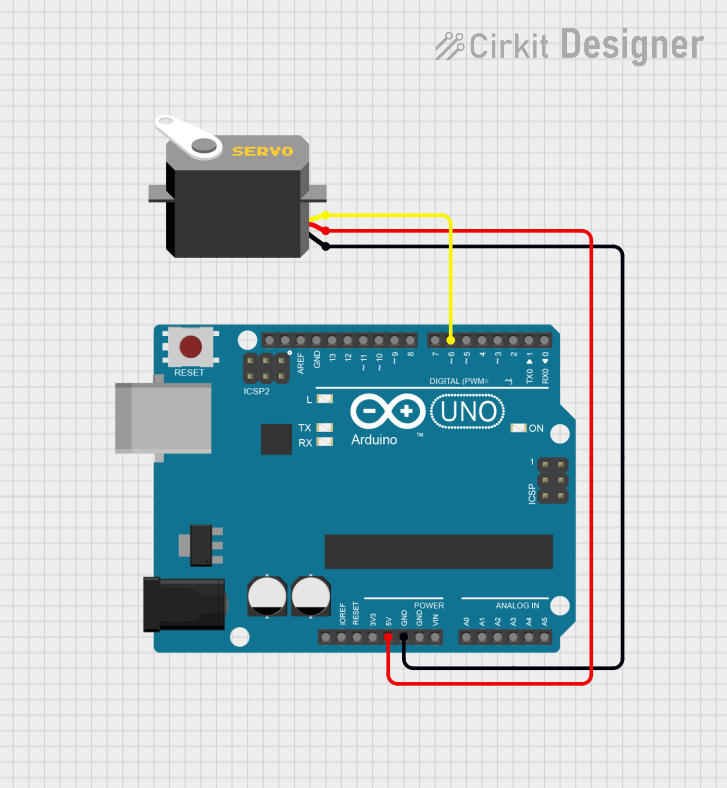
Example: Connecting a Servo to an Arduino UNO
Below is an example of how to control a servo using an Arduino UNO:
#include <Servo.h> // Include the Servo library

Servo myServo; // Create a Servo object

void setup() {
  myServo.attach(9); // Attach the servo to pin 9 on the Arduino
}

void loop() {
  myServo.write(0); // Move the servo to 0 degrees
  delay(1000);      // Wait for 1 second

  myServo.write(90); // Move the servo to 90 degrees
  delay(1000);       // Wait for 1 second

  myServo.write(180); // Move the servo to 180 degrees
  delay(1000);        // Wait for 1 second
}
Notes on the Code
- The
Servolibrary simplifies the process of generating PWM signals. - The
myServo.attach(9)function links the servo to pin 9. - The
myServo.write(angle)function sets the servo to a specific angle (0° to 180°).
Troubleshooting and FAQs
Common Issues and Solutions
Servo Not Moving
- Cause: Incorrect wiring or insufficient power supply.
- Solution: Double-check the connections and ensure the power supply meets the servo's requirements.
Jittery or Erratic Movement
- Cause: Unstable PWM signal or electrical noise.
- Solution: Use a decoupling capacitor near the servo's power pins and ensure the PWM signal is stable.
Overheating
- Cause: Overloading the servo or running it continuously at high torque.
- Solution: Reduce the load or use a servo with a higher torque rating.
Limited Range of Motion
- Cause: Mechanical obstruction or incorrect PWM signal.
- Solution: Check for physical obstructions and verify the pulse width range.
FAQs
Q: Can I power the servo directly from the Arduino?
A: While possible for small servos, it is recommended to use an external power supply to avoid overloading the Arduino.Q: How do I control a continuous rotation servo?
A: For continuous rotation servos, use themyServo.write()function with values around 90 for stop, less than 90 for one direction, and greater than 90 for the opposite direction.Q: Can I connect multiple servos to a single Arduino?
A: Yes, but ensure the power supply can handle the combined current draw of all servos.
This documentation provides a comprehensive guide to understanding and using a servo in various applications.