How to Use 2 Solid State Relay: Examples, Pinouts, and Specs
Introduction
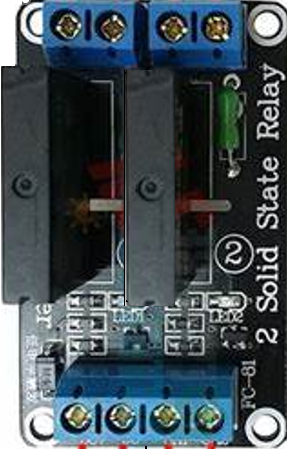
The 2 Solid State Relay (SSR) is an electronic component designed for high-speed, reliable switching of electrical loads without the mechanical wear and tear associated with traditional electromechanical relays. SSRs are widely used in various applications, including industrial automation, home automation, and temperature control systems, due to their ability to handle high power loads with precision and without noise.
Explore Projects Built with 2 Solid State Relay


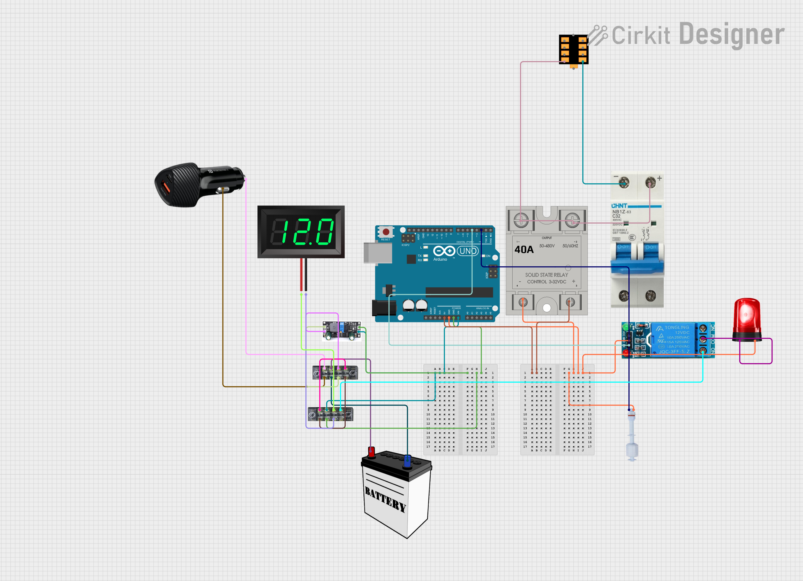

Explore Projects Built with 2 Solid State Relay
Technical Specifications
General Characteristics
- Control Voltage Range: Typically 3-32V DC
- Load Voltage Range: Typically 24-380V AC
- Current Rating: Up to several tens of Amperes, depending on the model
- Isolation Voltage: Typically >2500V
- Switching Speed: Instantaneous, usually in the microseconds range
- Operating Temperature: -30°C to +70°C
Pin Configuration and Descriptions
| Pin Number | Description | Notes |
|---|---|---|
| 1 | Control Voltage Input (+) | Connect to positive of DC control |
| 2 | Control Voltage Input (-) | Connect to negative of DC control |
| 3 | Load Voltage Output (Line) | Connect to AC load line |
| 4 | Load Voltage Output (Neutral) | Connect to AC load neutral |
Note: The pin configuration may vary depending on the manufacturer and model. Always refer to the manufacturer's datasheet for exact details.
Usage Instructions
Connecting to a Circuit
Control Circuit Connection:
- Connect the positive terminal of the control voltage source to Pin 1.
- Connect the negative terminal of the control voltage source to Pin 2.
Load Circuit Connection:
- Connect the line wire of the AC load to Pin 3.
- Connect the neutral wire of the AC load to Pin 4.
Best Practices
- Ensure the control voltage matches the SSR's specified range.
- Do not exceed the rated current and voltage for the load.
- Use heat sinks if the SSR is expected to handle loads near its maximum rating.
- Provide adequate ventilation to prevent overheating.
- Use snubber circuits if inductive loads are switched to prevent voltage spikes.
Troubleshooting and FAQs
Common Issues
SSR Not Switching On:
- Check if the control voltage is within the specified range.
- Verify connections to the control input terminals.
- Inspect for any visible damage to the SSR.
SSR Not Switching Off:
- This could be due to a shorted output semiconductor. Replace the SSR if necessary.
Overheating:
- Ensure the load does not exceed the SSR's rating.
- Improve ventilation or add a heat sink.
FAQs
Q: Can I use an SSR for both AC and DC loads? A: SSRs are typically designed for either AC or DC loads. Ensure you select the correct type for your application.
Q: How do I know if my SSR is functioning properly? A: Measure the voltage across the output terminals when the control voltage is applied. If the SSR is functioning, the output should be close to zero volts, indicating the load circuit is complete.
Q: Is it necessary to use a heat sink with an SSR? A: For high-current applications or when the SSR is enclosed in a space with limited airflow, a heat sink is recommended to dissipate heat and ensure reliable operation.
Example Code for Arduino UNO
// Example code to control a 2 Solid State Relay with an Arduino UNO

const int ssrPin = 7; // Connect the control input of the SSR to digital pin 7

void setup() {
  pinMode(ssrPin, OUTPUT); // Set the SSR pin as an output
}

void loop() {
  digitalWrite(ssrPin, HIGH); // Turn on the SSR (connects the load)
  delay(1000);                // Wait for 1 second
  digitalWrite(ssrPin, LOW);  // Turn off the SSR (disconnects the load)
  delay(1000);                // Wait for 1 second
}
Note: The above code is a simple example to demonstrate turning on and off an SSR with an Arduino. Always ensure that the control voltage from the Arduino matches the SSR's requirements and that the load connected to the SSR does not exceed its ratings.