
How to Use ADM1087: Examples, Pinouts, and Specs
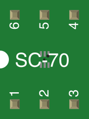
 Design with ADM1087 in Cirkit Designer
Introduction
The ADM1087 is a precision voltage reference and monitor designed to provide a stable and accurate output voltage for a wide range of electronic applications. This component ensures reliable voltage levels, making it ideal for use in systems requiring precise voltage regulation and monitoring. Its compact design and high accuracy make it suitable for power management, battery-operated devices, and industrial control systems.
Explore Projects Built with ADM1087
 Open Project in Cirkit Designer
 Open Project in Cirkit Designer
 Open Project in Cirkit Designer
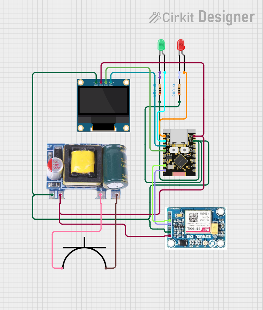 Open Project in Cirkit Designer
Explore Projects Built with ADM1087
Open Project in Cirkit DesignerOpen Project in Cirkit DesignerOpen Project in Cirkit DesignerOpen Project in Cirkit DesignerCommon Applications:
- Power supply monitoring and sequencing
- Battery-powered devices
- Industrial automation and control systems
- Microcontroller-based circuits
- Data acquisition systems
Technical Specifications
Key Technical Details:
- Input Voltage Range: 1.6 V to 5.5 V
- Output Voltage: Fixed at 0.6 V (typical)
- Quiescent Current: 5 µA (typical)
- Output Accuracy: ±1% over temperature range
- Operating Temperature Range: -40°C to +125°C
- Package Options: SOT-23-5
Pin Configuration and Descriptions:
The ADM1087 is available in a 5-pin SOT-23 package. The pinout and descriptions are as follows:
| Pin Number | Pin Name | Description |
|---|---|---|
| 1 | VCC | Power supply input (1.6 V to 5.5 V). |
| 2 | GND | Ground connection. |
| 3 | OUT | Precision voltage reference output (0.6 V typical). |
| 4 | EN | Enable input. High to enable the output. |
| 5 | NC | No connection (leave floating or connect to GND). |
Usage Instructions
How to Use the ADM1087 in a Circuit:
- Power Supply: Connect the VCC pin to a stable power source within the range of 1.6 V to 5.5 V. Ensure proper decoupling with a capacitor (e.g., 0.1 µF) close to the VCC pin to minimize noise.
- Ground Connection: Connect the GND pin to the circuit ground.
- Output Voltage: The OUT pin provides a stable 0.6 V reference. This can be used as a reference voltage for ADCs, DACs, or other precision circuits.
- Enable Pin: Drive the EN pin high to enable the output. If unused, connect it to VCC to keep the output always enabled.
- No Connection Pin: Leave the NC pin floating or connect it to GND for better stability.
Important Considerations:
- Bypass Capacitor: Always use a bypass capacitor (e.g., 0.1 µF ceramic) between VCC and GND to filter out noise and ensure stable operation.
- Load Current: The ADM1087 is designed for low-current applications. Avoid connecting it to high-current loads to prevent instability.
- Thermal Management: Ensure the component operates within the specified temperature range (-40°C to +125°C) to maintain accuracy.
Example: Using ADM1087 with Arduino UNO
The ADM1087 can be used as a reference voltage for the Arduino UNO's ADC. Below is an example of how to connect and use it:
Circuit Connections:
- Connect the ADM1087's VCC to the Arduino's 5V pin.
- Connect GND to the Arduino's GND.
- Connect the OUT pin to the Arduino's AREF pin.
- Connect the EN pin to the Arduino's 5V pin to enable the output.
Arduino Code Example:
// Example code to use ADM1087 as an external reference for Arduino ADC

void setup() {
  // Set the ADC reference to external (using ADM1087's 0.6V output)
  analogReference(EXTERNAL);

  // Initialize serial communication for debugging
  Serial.begin(9600);
}

void loop() {
  // Read an analog value from pin A0
  int sensorValue = analogRead(A0);

  // Convert the ADC value to voltage (0.6V reference, 10-bit ADC)
  float voltage = sensorValue * (0.6 / 1023.0);

  // Print the voltage to the Serial Monitor
  Serial.print("Voltage: ");
  Serial.print(voltage, 3); // Print with 3 decimal places
  Serial.println(" V");

  delay(1000); // Wait for 1 second before the next reading
}
Notes:
- Ensure the AREF pin is connected to the ADM1087's OUT pin before setting
analogReference(EXTERNAL). - Disconnect the AREF pin if switching back to the default reference voltage to avoid damage.
Troubleshooting and FAQs
Common Issues:
No Output Voltage:
- Cause: The EN pin is not connected or is held low.
- Solution: Ensure the EN pin is connected to VCC or driven high.
Unstable Output Voltage:
- Cause: Insufficient bypass capacitance on the VCC pin.
- Solution: Add a 0.1 µF ceramic capacitor close to the VCC pin.
Incorrect ADC Readings:
- Cause: AREF pin not properly connected to the ADM1087's OUT pin.
- Solution: Verify the connection between the AREF pin and the OUT pin.
Overheating:
- Cause: Operating outside the specified voltage or temperature range.
- Solution: Ensure the input voltage is within 1.6 V to 5.5 V and the ambient temperature is within -40°C to +125°C.
FAQs:
Can the ADM1087 drive high-current loads? No, the ADM1087 is designed for low-current applications. Use a buffer circuit if higher current is required.
What happens if the EN pin is left floating? The output will remain disabled. Always connect the EN pin to VCC or a control signal.
Can I use the ADM1087 with a 3.3 V system? Yes, the ADM1087 operates with input voltages as low as 1.6 V, making it compatible with 3.3 V systems.
Is the output voltage adjustable? No, the ADM1087 provides a fixed 0.6 V reference output.