How to Use Adafruit DotStar Strip 60M_B: Examples, Pinouts, and Specs
Introduction
The Adafruit DotStar Strip 60M_B is a high-density, digitally-addressable LED strip that provides advanced control of color and brightness, enabling the creation of intricate lighting effects. This strip is ideal for a wide range of applications, from DIY projects and art installations to commercial lighting and interactive displays.
Explore Projects Built with Adafruit DotStar Strip 60M_B
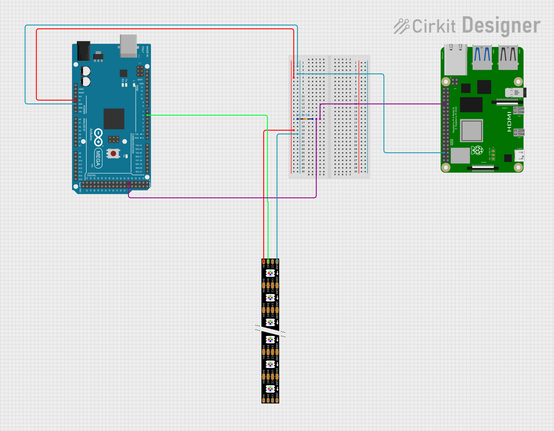
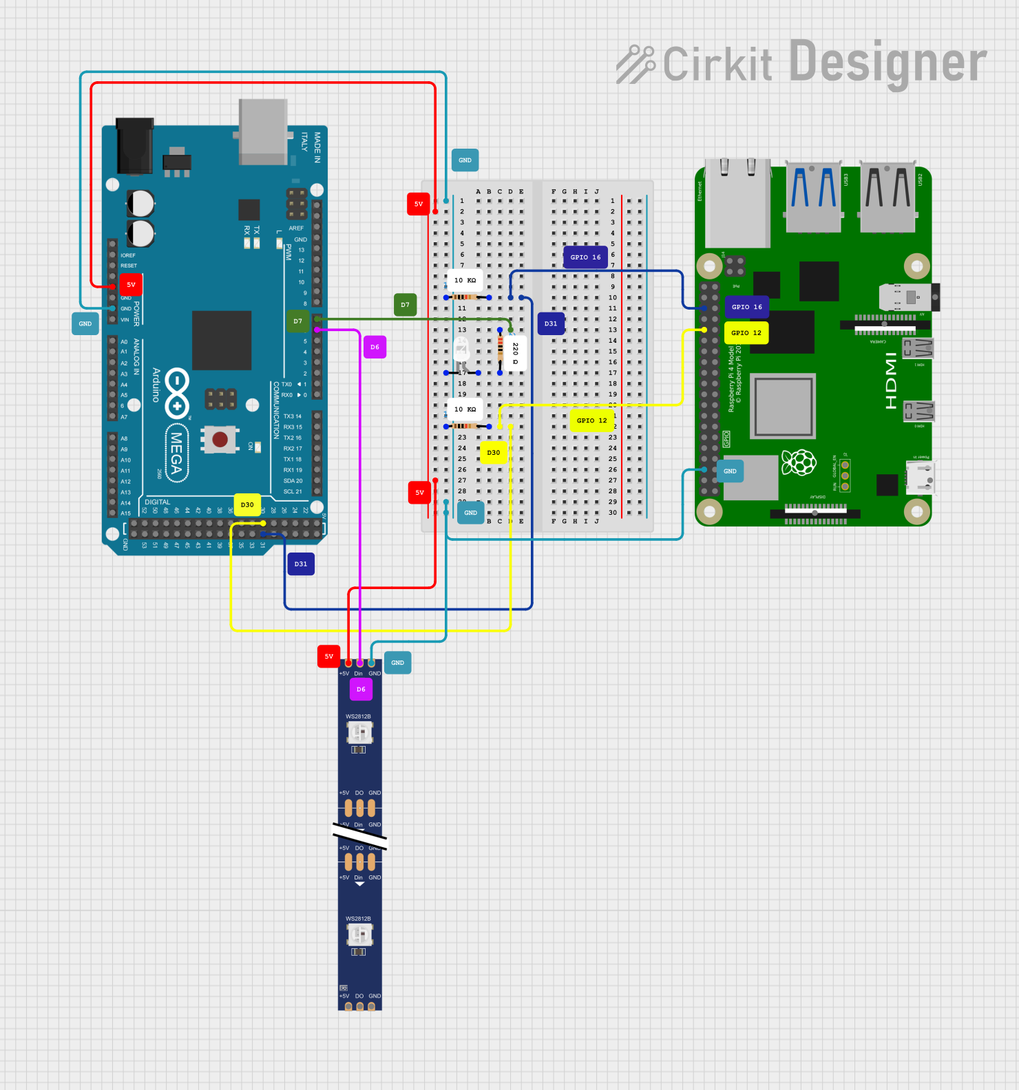
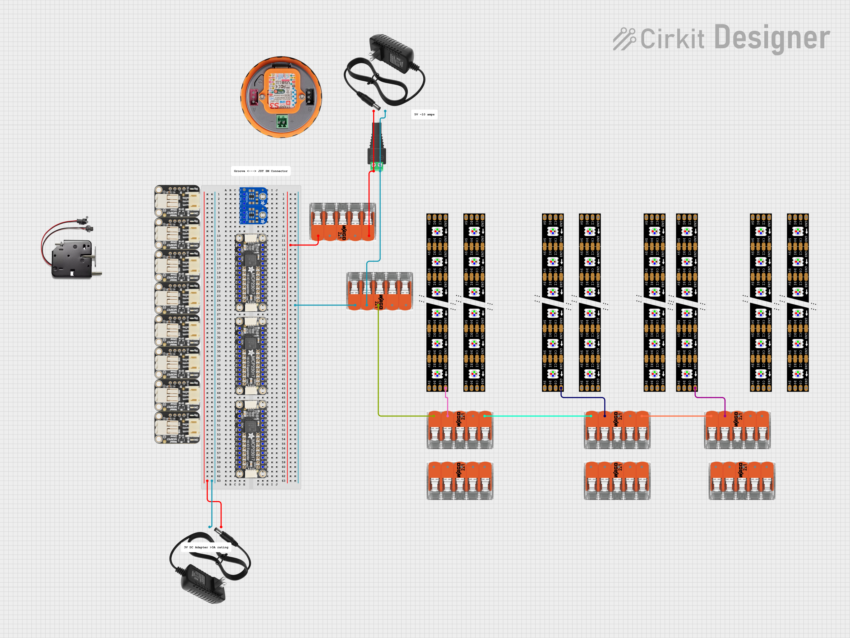

Explore Projects Built with Adafruit DotStar Strip 60M_B
Common Applications and Use Cases
- Decorative lighting for homes and commercial spaces
- Wearable electronics and fashion accessories
- Signage and backlit displays
- Stage design and theatrical lighting
- Prototyping and educational projects
Technical Specifications
Key Technical Details
- LED Density: 60 LEDs per meter
- Voltage: 5V DC
- Current: ~18mA per LED at full brightness
- Power Ratings: ~90W for a full 5-meter strip at full brightness
- Communication: Two-wire SPI-like protocol
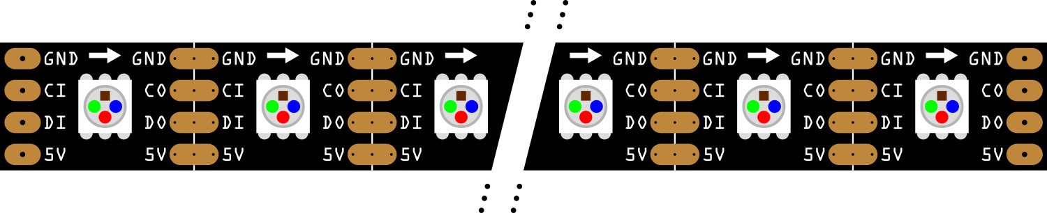
Pin Configuration and Descriptions
| Pin Number | Name | Description |
|---|---|---|
| 1 | 5V | Power supply voltage (5V DC) |
| 2 | GND | Ground connection |
| 3 | CI | Clock Input for LED data signal |
| 4 | DI | Data Input for LED data signal |
Usage Instructions
How to Use the Component in a Circuit
- Power Supply: Connect the 5V and GND pins to a suitable 5V power supply, ensuring that it can provide sufficient current for the number of LEDs you intend to use.
- Data Connection: Connect the CI (Clock Input) and DI (Data Input) to the microcontroller's digital output pins.
- Microcontroller Setup: Program the microcontroller to send data to the DotStar strip using the appropriate library and protocol.
Important Considerations and Best Practices
- Power Requirements: Calculate the total current requirement based on the number of LEDs and ensure the power supply can handle the load.
- Voltage Drop: For longer strips, be aware of voltage drop. Power the strip at both ends or inject power at multiple points along the strip.
- Heat Dissipation: Ensure proper heat dissipation to prevent overheating and damage to the LEDs.
- Data Signal Integrity: Keep the data and clock lines as short as possible to maintain signal integrity.
Example Code for Arduino UNO
#include <Adafruit_DotStar.h>
#include <SPI.h> // Use SPI library

#define NUMPIXELS 60 // Number of LEDs in strip
#define DATAPIN    4
#define CLOCKPIN   5

// Create DotStar object:
Adafruit_DotStar strip = Adafruit_DotStar(
  NUMPIXELS, DATAPIN, CLOCKPIN, DOTSTAR_BRG);

void setup() {
  strip.begin(); // Initialize pins for output
  strip.show();  // Turn all LEDs off ASAP
}

void loop() {
  int i;

  // Some example procedures showing how to display to the pixels:
  for(i=0; i<strip.numPixels(); i++) { // For each pixel...
    strip.setPixelColor(i, strip.Color(0, 255, 0)); // Set pixel's color (in this case: Green)
    strip.show();   // Update strip to match
    delay(50);      // Pause for a moment
  }
}
Troubleshooting and FAQs
Common Issues
- LEDs Not Lighting Up: Check power supply connections and ensure the microcontroller is correctly programmed and connected.
- Incorrect Colors: Verify that the data and clock pins are connected to the correct pins on the microcontroller.
- Flickering LEDs: This may be due to insufficient power or noise in the data signal. Check power supply and data line integrity.
Solutions and Tips for Troubleshooting
- Power Issues: Use a multimeter to check the voltage at the start and end of the strip.
- Data and Clock Connections: Double-check the connections and ensure they are secure.
- Code Verification: Ensure that the code uploaded to the microcontroller matches the intended design and uses the correct library functions.
FAQs
Q: Can I cut the strip to a shorter length? A: Yes, the strip can be cut at designated points, usually marked with a line and scissor icon.
Q: How do I attach multiple strips together? A: Strips can be soldered together at the designated solder pads for extending length.
Q: What is the maximum length I can use without experiencing voltage drop? A: This depends on the power supply and the gauge of the power wires, but typically, you should inject power every 1 to 2 meters to prevent voltage drop.
Q: Can I control the strip with a 3.3V microcontroller? A: While the strip is rated for 5V, many users have successfully driven DotStar strips with 3.3V logic. However, for reliable operation, level shifting to 5V may be necessary.