Cirkit Designer Logo
Cirkit Designer
Your all-in-one circuit design IDE
Home / 
Component Documentation

How to Use gy-us-42: Examples, Pinouts, and Specs

Image of gy-us-42
Cirkit Designer LogoDesign with gy-us-42 in Cirkit Designer

Introduction

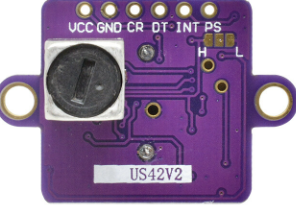
The GY-US-42 is an ultrasonic distance sensor designed to measure the distance to an object using sonar technology. It emits ultrasonic waves and calculates the time taken for the echo to return, providing precise distance measurements. This sensor is widely used in applications such as robotics, obstacle detection, level measurement, and proximity sensing. Its compact design and high accuracy make it a popular choice for both hobbyists and professionals.

Explore Projects Built with gy-us-42

Use Cirkit Designer to design, explore, and prototype these projects online. Some projects support real-time simulation. Click "Open Project" to start designing instantly!
Satellite-Based Timing and Navigation System with SDR and Atomic Clock Synchronization
Image of GPS 시스템 측정 구성도_Confirm: A project utilizing gy-us-42 in a practical application
This circuit appears to be a complex system involving power supply management, GPS and timing synchronization, and data communication. It includes a SI-TEX G1 Satellite Compass for GPS data, an XHTF1021 Atomic Rubidium Clock for precise timing, and Ettus USRP B200 units for software-defined radio communication. Power is supplied through various SMPS units and distributed via terminal blocks and DC jacks. Data communication is facilitated by Beelink MINI S12 N95 computers, RS232 splitters, and a 1000BASE-T Media Converter for network connectivity. RF Directional Couplers are used to interface antennas with the USRP units, and the entire system is likely contained within cases for protection and organization.
Cirkit Designer LogoOpen Project in Cirkit Designer
ESP32-Based Automated Landing Gear System with Ultrasonic Sensor and LCD Display
Image of LANDING GEAR MECHANISMS: A project utilizing gy-us-42 in a practical application
This circuit is an automated landing gear system for a model aircraft, utilizing an ESP32 microcontroller to control two servos based on input from an ultrasonic sensor and a toggle switch. The system displays distance measurements and gear status on a 16x2 LCD screen via an I2C interface.
Cirkit Designer LogoOpen Project in Cirkit Designer
ESP32-Based Ultrasonic Distance Measurement System with GSM Reporting
Image of notification sms: A project utilizing gy-us-42 in a practical application
This circuit is designed to measure distances with three ultrasonic sensors and transmit the data via GSM using an ESP32 microcontroller. It is powered by a battery with a voltage regulation provided by an XL4015 buck converter.
Cirkit Designer LogoOpen Project in Cirkit Designer
Cellular-Enabled IoT Device with Real-Time Clock and Power Management
Image of LRCM PHASE 2 BASIC: A project utilizing gy-us-42 in a practical application
This circuit features a LilyGo-SIM7000G module for cellular communication and GPS functionality, interfaced with an RTC DS3231 for real-time clock capabilities. It includes voltage sensing through two voltage sensor modules, and uses an 8-channel opto-coupler for isolating different parts of the circuit. Power management is handled by a buck converter connected to a DC power source and batteries, with a fuse for protection and a rocker switch for on/off control. Additionally, there's an LED for indication purposes.
Cirkit Designer LogoOpen Project in Cirkit Designer

Explore Projects Built with gy-us-42

Use Cirkit Designer to design, explore, and prototype these projects online. Some projects support real-time simulation. Click "Open Project" to start designing instantly!
Image of GPS 시스템 측정 구성도_Confirm: A project utilizing gy-us-42 in a practical application
Satellite-Based Timing and Navigation System with SDR and Atomic Clock Synchronization
This circuit appears to be a complex system involving power supply management, GPS and timing synchronization, and data communication. It includes a SI-TEX G1 Satellite Compass for GPS data, an XHTF1021 Atomic Rubidium Clock for precise timing, and Ettus USRP B200 units for software-defined radio communication. Power is supplied through various SMPS units and distributed via terminal blocks and DC jacks. Data communication is facilitated by Beelink MINI S12 N95 computers, RS232 splitters, and a 1000BASE-T Media Converter for network connectivity. RF Directional Couplers are used to interface antennas with the USRP units, and the entire system is likely contained within cases for protection and organization.
Cirkit Designer LogoOpen Project in Cirkit Designer
Image of LANDING GEAR MECHANISMS: A project utilizing gy-us-42 in a practical application
ESP32-Based Automated Landing Gear System with Ultrasonic Sensor and LCD Display
This circuit is an automated landing gear system for a model aircraft, utilizing an ESP32 microcontroller to control two servos based on input from an ultrasonic sensor and a toggle switch. The system displays distance measurements and gear status on a 16x2 LCD screen via an I2C interface.
Cirkit Designer LogoOpen Project in Cirkit Designer
Image of notification sms: A project utilizing gy-us-42 in a practical application
ESP32-Based Ultrasonic Distance Measurement System with GSM Reporting
This circuit is designed to measure distances with three ultrasonic sensors and transmit the data via GSM using an ESP32 microcontroller. It is powered by a battery with a voltage regulation provided by an XL4015 buck converter.
Cirkit Designer LogoOpen Project in Cirkit Designer
Image of LRCM PHASE 2 BASIC: A project utilizing gy-us-42 in a practical application
Cellular-Enabled IoT Device with Real-Time Clock and Power Management
This circuit features a LilyGo-SIM7000G module for cellular communication and GPS functionality, interfaced with an RTC DS3231 for real-time clock capabilities. It includes voltage sensing through two voltage sensor modules, and uses an 8-channel opto-coupler for isolating different parts of the circuit. Power management is handled by a buck converter connected to a DC power source and batteries, with a fuse for protection and a rocker switch for on/off control. Additionally, there's an LED for indication purposes.
Cirkit Designer LogoOpen Project in Cirkit Designer

Technical Specifications

  • Operating Voltage: 3.3V to 5V DC
  • Operating Current: ≤ 15mA
  • Measuring Range: 2cm to 450cm
  • Measuring Accuracy: ±1mm
  • Output Modes: UART (serial) or PWM
  • Communication Protocol: UART (9600 baud rate)
  • Operating Temperature: -15°C to 60°C
  • Dimensions: 45mm x 20mm x 15mm

Pin Configuration and Descriptions

The GY-US-42 sensor has 4 pins, as described in the table below:

Pin Number Pin Name Description
1 VCC Power supply input (3.3V to 5V DC).
2 GND Ground connection.
3 TXD UART transmit pin for serial communication.
4 RXD UART receive pin for serial communication.

Alternatively, the sensor can operate in PWM mode. In this case, the TXD pin outputs a PWM signal representing the measured distance.

Usage Instructions

Connecting the GY-US-42 to an Arduino UNO

The GY-US-42 can be easily interfaced with an Arduino UNO using its UART communication mode. Follow these steps to connect and use the sensor:

  1. Wiring:

    • Connect the VCC pin of the GY-US-42 to the 5V pin on the Arduino.
    • Connect the GND pin of the GY-US-42 to the GND pin on the Arduino.
    • Connect the TXD pin of the GY-US-42 to the Arduino's RX (Pin 0).
    • Connect the RXD pin of the GY-US-42 to the Arduino's TX (Pin 1).
  2. Arduino Code: Use the following example code to read distance measurements from the GY-US-42:

    // GY-US-42 Ultrasonic Distance Sensor Example Code
    // This code reads distance data from the sensor via UART and displays it
    // on the Serial Monitor.
    
    void setup() {
      Serial.begin(9600); // Initialize serial communication at 9600 baud
      delay(100);         // Allow time for the sensor to initialize
    }
    
    void loop() {
      if (Serial.available() > 0) { // Check if data is available from the sensor
        int highByte = Serial.read(); // Read the high byte of the distance
        int lowByte = Serial.read();  // Read the low byte of the distance
        int distance = (highByte << 8) + lowByte; // Combine high and low bytes
    
        // Display the distance in centimeters
        Serial.print("Distance: ");
        Serial.print(distance);
        Serial.println(" cm");
      }
      delay(100); // Add a small delay to avoid overwhelming the sensor
    }
    

Important Considerations

  • Ensure the sensor is powered within its operating voltage range (3.3V to 5V). Exceeding this range may damage the sensor.
  • Avoid placing the sensor in environments with excessive noise or vibrations, as this may affect measurement accuracy.
  • When using the sensor in PWM mode, refer to the datasheet for details on interpreting the PWM signal.

Troubleshooting and FAQs

Common Issues and Solutions

  1. No Data Received from the Sensor:

    • Cause: Incorrect wiring or baud rate mismatch.
    • Solution: Double-check the wiring connections and ensure the Arduino's baud rate is set to 9600.
  2. Inaccurate Distance Measurements:

    • Cause: Obstructions or reflective surfaces near the sensor.
    • Solution: Ensure the sensor has a clear line of sight to the target object. Avoid using the sensor near highly reflective or absorbent surfaces.
  3. Sensor Not Powering On:

    • Cause: Insufficient power supply.
    • Solution: Verify that the power supply provides a stable voltage between 3.3V and 5V.

FAQs

Q1: Can the GY-US-42 measure distances below 2cm?
A1: No, the minimum measurable distance for the GY-US-42 is 2cm. Objects closer than this may not be detected accurately.

Q2: Can I use the GY-US-42 with a 3.3V microcontroller?
A2: Yes, the GY-US-42 is compatible with 3.3V systems. Ensure the power supply and logic levels match the microcontroller's specifications.

Q3: How do I switch between UART and PWM modes?
A3: The GY-US-42 defaults to UART mode. Refer to the sensor's datasheet for instructions on enabling PWM mode if needed.