How to Use ESP32 (30 pin): Examples, Pinouts, and Specs
Introduction
The ESP32 is a powerful microcontroller with built-in Wi-Fi and Bluetooth capabilities, making it an excellent choice for Internet of Things (IoT) applications and embedded systems. With its 30-pin configuration, the ESP32 offers a wide range of input/output (I/O) options, enabling developers to connect sensors, actuators, and other peripherals with ease. Its dual-core processor and low-power consumption make it suitable for both high-performance and energy-efficient designs.
Explore Projects Built with ESP32 (30 pin)


Explore Projects Built with ESP32 (30 pin)
Common Applications and Use Cases
- IoT devices (e.g., smart home systems, wearables)
- Wireless communication (Wi-Fi and Bluetooth)
- Data logging and remote monitoring
- Robotics and automation
- Prototyping and development of embedded systems
Technical Specifications
The ESP32 (30 pin) microcontroller is packed with features that make it versatile and powerful. Below are its key technical specifications:
Key Technical Details
- Processor: Dual-core Xtensa® 32-bit LX6 CPU
- Clock Speed: Up to 240 MHz
- Flash Memory: 4 MB (varies by model)
- SRAM: 520 KB
- Wi-Fi: 802.11 b/g/n
- Bluetooth: v4.2 BR/EDR and BLE
- Operating Voltage: 3.3V
- Input Voltage Range: 5V (via USB) or 7-12V (via VIN pin)
- GPIO Pins: 30 pins (including ADC, DAC, PWM, I2C, SPI, UART)
- Power Consumption: Ultra-low power consumption in deep sleep mode (~10 µA)
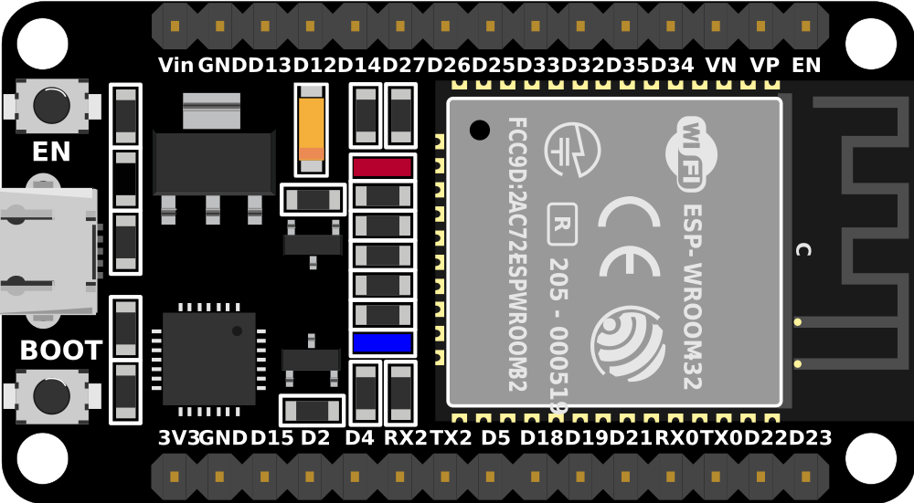
Pin Configuration and Descriptions
The ESP32 (30 pin) has a variety of pins for different functionalities. Below is a table summarizing the pin configuration:
| Pin Name | Function | Description |
|---|---|---|
| VIN | Power Input | Accepts 7-12V input to power the ESP32. |
| GND | Ground | Common ground for the circuit. |
| 3V3 | Power Output | Provides 3.3V output for external components. |
| EN | Enable | Enables or disables the chip (active high). |
| GPIO0 | General Purpose I/O, Boot Mode | Used for I/O or to enter bootloader mode during programming. |
| GPIO1 (TX) | UART TX | Transmit pin for UART communication. |
| GPIO3 (RX) | UART RX | Receive pin for UART communication. |
| GPIO2 | General Purpose I/O, ADC, PWM | Can be used for digital I/O, ADC, or PWM. |
| GPIO4 | General Purpose I/O, ADC, PWM | Can be used for digital I/O, ADC, or PWM. |
| GPIO5 | General Purpose I/O, ADC, PWM | Can be used for digital I/O, ADC, or PWM. |
| GPIO12-15 | General Purpose I/O, ADC, PWM | Multi-purpose pins for digital I/O, ADC, or PWM. |
| GPIO16-19 | General Purpose I/O, SPI | Can be used for digital I/O or SPI communication. |
| GPIO21-23 | General Purpose I/O, I2C | Can be used for digital I/O or I2C communication (SDA/SCL). |
| GPIO25-27 | General Purpose I/O, DAC, ADC | Can be used for digital I/O, DAC, or ADC. |
| GPIO32-39 | General Purpose I/O, ADC | Can be used for digital I/O or ADC. |
| A0-A5 | Analog Input | Analog input pins for reading sensor data. |
| RST | Reset | Resets the microcontroller. |
Usage Instructions
How to Use the ESP32 in a Circuit
Powering the ESP32:
- Use the VIN pin to supply 7-12V, or connect a USB cable to the micro-USB port for 5V input.
- Ensure the GND pin is connected to the ground of your circuit.
Connecting Peripherals:
- Use GPIO pins for digital I/O, ADC pins for analog input, and DAC pins for analog output.
- For communication, use UART (TX/RX), I2C (SDA/SCL), or SPI pins as needed.
Programming the ESP32:
- Install the ESP32 board package in the Arduino IDE or use the ESP-IDF framework.
- Connect the ESP32 to your computer via USB and select the appropriate COM port in the IDE.
Uploading Code:
- Press the "Upload" button in the Arduino IDE to flash your code to the ESP32.
- If required, hold the BOOT button during the upload process.
Important Considerations and Best Practices
- Always use a level shifter when interfacing 5V logic devices with the ESP32, as it operates at 3.3V.
- Avoid drawing excessive current from the 3V3 pin to prevent instability.
- Use decoupling capacitors near the power pins to reduce noise.
- Ensure proper grounding to avoid communication errors.
Example Code for Arduino UNO Integration
Below is an example of how to use the ESP32 to read an analog sensor and send data via Wi-Fi:
#include <WiFi.h>

// Replace with your network credentials
const char* ssid = "Your_SSID";
const char* password = "Your_PASSWORD";

void setup() {
  Serial.begin(115200); // Initialize serial communication at 115200 baud
  WiFi.begin(ssid, password); // Connect to Wi-Fi network

  // Wait for connection
  while (WiFi.status() != WL_CONNECTED) {
    delay(1000);
    Serial.println("Connecting to Wi-Fi...");
  }
  Serial.println("Connected to Wi-Fi!");
}

void loop() {
  int sensorValue = analogRead(34); // Read analog value from GPIO34 (A0)
  Serial.print("Sensor Value: ");
  Serial.println(sensorValue); // Print the sensor value to the Serial Monitor
  delay(1000); // Wait for 1 second before reading again
}
Troubleshooting and FAQs
Common Issues and Solutions
ESP32 Not Connecting to Wi-Fi:
- Double-check the SSID and password in your code.
- Ensure the Wi-Fi network is operational and within range.
- Restart the ESP32 and your router if necessary.
Upload Fails or Timeout Error:
- Ensure the correct COM port is selected in the Arduino IDE.
- Hold the BOOT button while uploading the code.
- Check the USB cable for proper connection and functionality.
Unstable Operation or Random Resets:
- Verify that the power supply provides sufficient current (at least 500 mA).
- Use decoupling capacitors to stabilize the power supply.
GPIO Pin Not Responding:
- Confirm that the pin is not being used for another function (e.g., boot mode).
- Check for loose connections or damaged components.
FAQs
Q: Can the ESP32 operate on battery power?
A: Yes, the ESP32 can be powered by a LiPo battery connected to the VIN pin. Ensure proper voltage regulation.Q: How do I use the ESP32's Bluetooth functionality?
A: Use theBluetoothSeriallibrary in the Arduino IDE or the ESP-IDF framework to implement Bluetooth communication.Q: Can I use the ESP32 with 5V sensors?
A: Yes, but you must use a level shifter to convert 5V signals to 3.3V to avoid damaging the ESP32.
By following this documentation, you can effectively utilize the ESP32 (30 pin) microcontroller in your projects.