How to Use 2s BMS: Examples, Pinouts, and Specs
Introduction
The 2s BMS (Battery Management System) is an essential component for managing and protecting a 2-cell series lithium-ion battery pack. It ensures the longevity and safety of the battery pack by monitoring cell voltages, balancing the charge between cells, and providing critical protections against overcharging, over-discharging, and overcurrent conditions. Common applications include portable electronics, electric vehicles, and DIY projects involving rechargeable battery packs.
Explore Projects Built with 2s BMS


Explore Projects Built with 2s BMS
Technical Specifications
Key Technical Details
- Voltage Range: Typically 6V - 8.4V (for 2-cell Li-ion configuration)
- Max Charging Voltage: 8.4V (4.2V per cell)
- Max Continuous Discharge Current: Varies by model (e.g., 5A, 10A, 20A)
- Max Continuous Charge Current: Varies by model (e.g., 2A, 5A)
- Balance Current: Typically around 60mA per cell
- Overcharge Protection Threshold: 4.25V ± 0.05V per cell
- Over-discharge Protection Threshold: 2.7V ± 0.1V per cell
- Operating Temperature Range: -40°C to +85°C
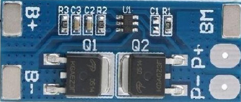
Pin Configuration and Descriptions
| Pin Number | Description | Notes |
|---|---|---|
| 1 | B+ (Battery Positive) | Connect to battery positive |
| 2 | BM (Battery Mid-point) | Connect to the junction between cells |
| 3 | B- (Battery Negative) | Connect to battery negative |
| 4 | P+ (Output/Charge Positive) | Connect to load/charger positive |
| 5 | P- (Output/Charge Negative) | Connect to load/charger negative |
Usage Instructions
Integrating the 2s BMS into a Circuit
Battery Connection:
- Connect the positive terminal of the first cell to B+.
- Connect the negative terminal of the first cell to the positive terminal of the second cell, and then connect this junction to BM.
- Connect the negative terminal of the second cell to B-.
Load/Charger Connection:
- Connect the positive terminal of the load or charger to P+.
- Connect the negative terminal of the load or charger to P-.
Important Considerations and Best Practices
- Current Rating: Ensure the BMS current rating matches or exceeds the maximum current draw of your application.
- Wiring: Use appropriate gauge wires to handle the expected current.
- Temperature: Avoid exposing the BMS to temperatures outside its operating range.
- Charging: Use a charger with a voltage that does not exceed the BMS's max charging voltage.
- Mounting: Secure the BMS to prevent movement and potential shorts.
Troubleshooting and FAQs
Common Issues and Solutions
Battery Not Charging:
- Check connections to ensure proper polarity and secure contacts.
- Verify that the charger is functioning and within the specified voltage range.
Battery Drains Quickly:
- Ensure that the cells are balanced. Imbalance can cause premature cut-off.
- Check for excessive current draw from the connected load.
BMS Cuts Off Unexpectedly:
- Verify that the load does not exceed the BMS's overcurrent protection threshold.
- Check if the battery cells are within their voltage range (not overcharged or over-discharged).
FAQs
Q: Can I bypass the BMS for a higher discharge rate?
- A: Bypassing the BMS is not recommended as it removes critical protections.
Q: How do I know if the BMS is balancing the cells?
- A: Some BMS boards have status LEDs that indicate when balancing is active. Otherwise, measuring the cell voltages can show if they are being balanced.
Q: What should I do if one cell is consistently lower than the other?
- A: Replace the cell if it's damaged or consider manually balancing the cells before allowing the BMS to take over.
Example Arduino Code for Monitoring BMS
// This example assumes the use of an external ADC or voltage sensor connected to the Arduino
// to read the voltages of the individual cells.

#include <Wire.h>

const int cell1Pin = A0; // Analog pin connected to cell 1 voltage divider
const int cell2Pin = A1; // Analog pin connected to cell 2 voltage divider

void setup() {
  Serial.begin(9600);
}

void loop() {
  int cell1VoltageRaw = analogRead(cell1Pin);
  int cell2VoltageRaw = analogRead(cell2Pin);

  float cell1Voltage = cell1VoltageRaw * (5.0 / 1023.0); // Convert to actual voltage
  float cell2Voltage = cell2VoltageRaw * (5.0 / 1023.0); // Convert to actual voltage

  Serial.print("Cell 1 Voltage: ");
  Serial.print(cell1Voltage);
  Serial.println(" V");

  Serial.print("Cell 2 Voltage: ");
  Serial.print(cell2Voltage);
  Serial.println(" V");

  // Add logic to check if voltages are within the safe range
  // and take action if they are not.

  delay(1000); // Wait for 1 second before reading again
}
Note: The above code is a simple example for monitoring purposes only and does not interact directly with the BMS. It assumes the use of additional hardware for voltage sensing and appropriate scaling factors for voltage dividers. Always ensure that the input voltage does not exceed the Arduino's maximum voltage rating for analog inputs.