
How to Use IA LENS: Examples, Pinouts, and Specs
 Design with IA LENS in Cirkit Designer
Introduction
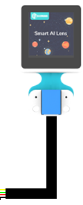
The IA Lens (Intelligent Augmented Lens) is an advanced optical component designed to integrate digital overlays with real-world views, enhancing visual information for users. Manufactured by Arduino with the part ID "UNO," this lens is a key component in augmented reality (AR) systems. It enables seamless interaction between physical environments and digital data, making it ideal for applications requiring real-time visual augmentation.
Explore Projects Built with IA LENS
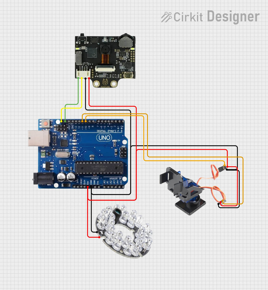 Open Project in Cirkit Designer
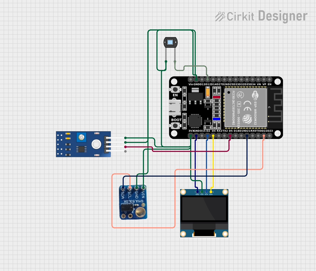 Open Project in Cirkit Designer
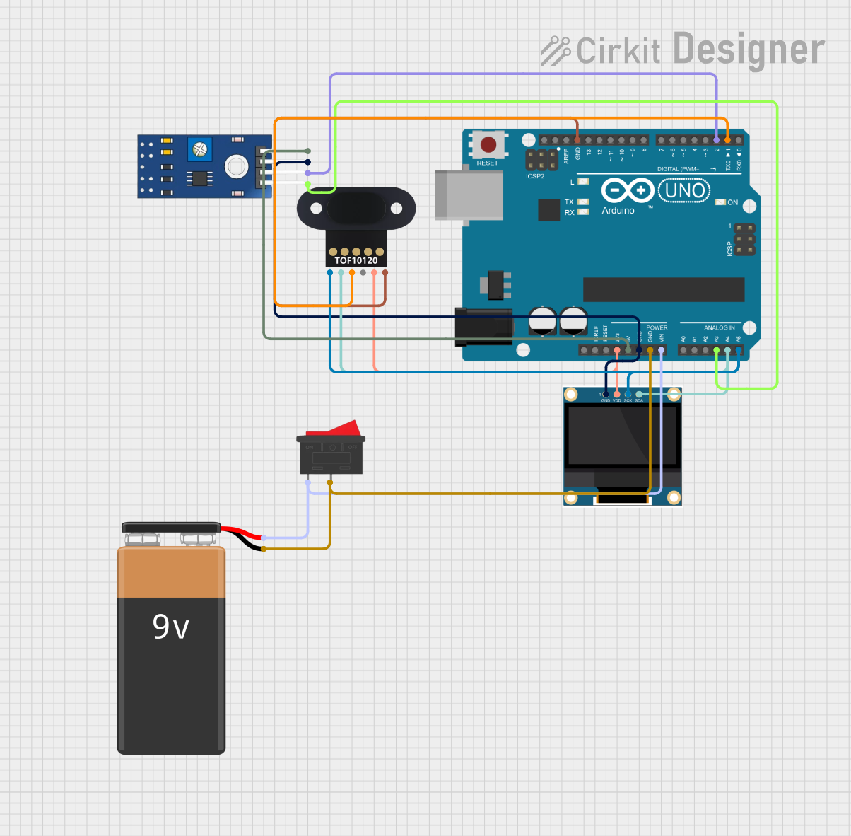 Open Project in Cirkit Designer
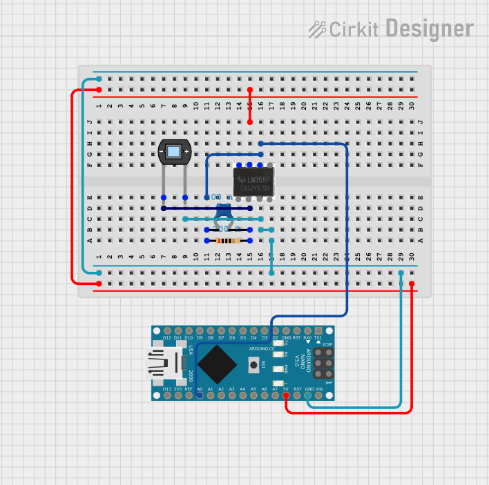 Open Project in Cirkit Designer
Explore Projects Built with IA LENS
Open Project in Cirkit DesignerOpen Project in Cirkit DesignerOpen Project in Cirkit DesignerOpen Project in Cirkit DesignerCommon Applications and Use Cases
- Augmented Reality (AR) Devices: Used in AR headsets and glasses for overlaying digital content.
- Medical Imaging: Enhances visualization during surgeries or diagnostics.
- Industrial Maintenance: Provides real-time instructions and schematics for complex machinery.
- Education and Training: Offers interactive learning experiences with digital overlays.
- Gaming and Entertainment: Immersive AR gaming and interactive media experiences.
Technical Specifications
Key Technical Details
| Parameter | Value |
|---|---|
| Manufacturer | Arduino |
| Part ID | UNO |
| Lens Type | Intelligent Augmented Lens |
| Field of View (FOV) | 90° |
| Resolution | 1920 x 1080 pixels |
| Refresh Rate | 60 Hz |
| Power Supply Voltage | 3.3V - 5V |
| Communication Interface | I2C |
| Operating Temperature | -10°C to 50°C |
| Dimensions | 50mm x 30mm x 10mm |
Pin Configuration and Descriptions
The IA Lens module includes a 6-pin interface for communication and power. Below is the pin configuration:
| Pin Number | Pin Name | Description |
|---|---|---|
| 1 | VCC | Power supply input (3.3V - 5V) |
| 2 | GND | Ground connection |
| 3 | SDA | I2C data line for communication |
| 4 | SCL | I2C clock line for communication |
| 5 | INT | Interrupt pin for event signaling |
| 6 | RESET | Resets the IA Lens module |
Usage Instructions
How to Use the IA Lens in a Circuit
- Power Connection: Connect the
VCCpin to a 3.3V or 5V power source and theGNDpin to the ground. - I2C Communication: Connect the
SDAandSCLpins to the corresponding I2C pins on your microcontroller (e.g., Arduino UNO). - Interrupt Handling: Use the
INTpin to detect events or notifications from the IA Lens. - Reset Functionality: Connect the
RESETpin to a digital output pin on the microcontroller for resetting the module when needed.
Important Considerations and Best Practices
- Ensure the power supply voltage is within the specified range (3.3V - 5V) to avoid damage.
- Use pull-up resistors (typically 4.7kΩ) on the
SDAandSCLlines for proper I2C communication. - Avoid exposing the lens to direct sunlight or extreme temperatures to maintain performance.
- Clean the lens surface with a microfiber cloth to prevent scratches or smudges.
Example Code for Arduino UNO
Below is an example code snippet to initialize and use the IA Lens with an Arduino UNO:
#include <Wire.h> // Include the Wire library for I2C communication

#define IA_LENS_ADDRESS 0x3C // I2C address of the IA Lens module

void setup() {
  Wire.begin(); // Initialize I2C communication
  Serial.begin(9600); // Start serial communication for debugging

  // Initialize the IA Lens
  Wire.beginTransmission(IA_LENS_ADDRESS);
  Wire.write(0x01); // Example command to initialize the lens
  if (Wire.endTransmission() == 0) {
    Serial.println("IA Lens initialized successfully.");
  } else {
    Serial.println("Failed to initialize IA Lens.");
  }
}

void loop() {
  // Example: Read data from the IA Lens
  Wire.requestFrom(IA_LENS_ADDRESS, 2); // Request 2 bytes of data
  if (Wire.available() == 2) {
    int data1 = Wire.read(); // Read the first byte
    int data2 = Wire.read(); // Read the second byte
    Serial.print("Data received: ");
    Serial.print(data1);
    Serial.print(", ");
    Serial.println(data2);
  }
  delay(1000); // Wait for 1 second before the next read
}
Troubleshooting and FAQs
Common Issues and Solutions
IA Lens Not Responding
- Cause: Incorrect I2C wiring or address mismatch.
- Solution: Verify the
SDAandSCLconnections and ensure the I2C address matches the module's default address (0x3C).
Distorted or No Augmented Display
- Cause: Dirty or damaged lens surface.
- Solution: Clean the lens with a microfiber cloth and inspect for physical damage.
Module Overheating
- Cause: Operating outside the recommended temperature range.
- Solution: Ensure the module is used within the specified temperature range (-10°C to 50°C).
I2C Communication Errors
- Cause: Missing pull-up resistors on the I2C lines.
- Solution: Add 4.7kΩ pull-up resistors to the
SDAandSCLlines.
FAQs
Q: Can the IA Lens be used with other microcontrollers besides Arduino UNO?
A: Yes, the IA Lens can be used with any microcontroller that supports I2C communication.Q: What is the maximum cable length for I2C communication?
A: For reliable communication, keep the cable length under 1 meter.Q: Is the IA Lens compatible with 5V logic levels?
A: Yes, the IA Lens supports both 3.3V and 5V logic levels.Q: How do I reset the IA Lens module?
A: Toggle theRESETpin low for at least 100ms and then set it high to reset the module.
This documentation provides all the necessary details to get started with the IA Lens and troubleshoot common issues effectively.