Cirkit Designer Logo
Cirkit Designer
Your all-in-one circuit design IDE
Home / 
Component Documentation

How to Use BRIDGE - 1N4007: Examples, Pinouts, and Specs

Image of BRIDGE - 1N4007
Cirkit Designer LogoDesign with BRIDGE - 1N4007 in Cirkit Designer

Introduction

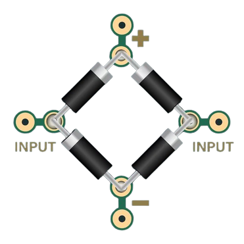
The BRIDGE - 1N4007 is a full-wave bridge rectifier that converts an alternating current (AC) input into a direct current (DC) output. This electronic component is widely used in power supply circuits to provide a stable DC voltage from an AC source. Common applications include battery charging systems, DC power supplies, and any electronic device that requires a rectified DC input.

Explore Projects Built with BRIDGE - 1N4007

Use Cirkit Designer to design, explore, and prototype these projects online. Some projects support real-time simulation. Click "Open Project" to start designing instantly!
NPN Transistor-Based Signal Interface with Relimate Connectors
Image of Mini cross: A project utilizing BRIDGE - 1N4007 in a practical application
This circuit appears to be a simple transistor-based switching circuit with multiple NPN transistors and resistors, interfaced through relimate connectors. The transistors are likely used to control the flow of current through various parts of the circuit, possibly for switching or amplification purposes, with the relimate connectors providing external connections for power and signal lines.
Cirkit Designer LogoOpen Project in Cirkit Designer
LED Array with Push Switch Control and Voltage Regulation
Image of Transformer safty device complete: A project utilizing BRIDGE - 1N4007 in a practical application
This circuit is a power supply and control system that steps down 220V AC to 24V AC using a transformer, rectifies it to DC using a bridge rectifier, and regulates it to 5V DC. It includes multiple LEDs controlled by push switches and a relay, with a capacitor for smoothing the output.
Cirkit Designer LogoOpen Project in Cirkit Designer
Piezo Sensor-Based LED Indicator with Pushbutton Control
Image of project: A project utilizing BRIDGE - 1N4007 in a practical application
This circuit is a rectifier and indicator system that uses multiple 1N4007 diodes to rectify an AC signal, a piezo sensor for signal detection, and a pushbutton to control the circuit. The rectified signal is filtered by an electrolytic capacitor and a resistor, and the presence of the signal is indicated by a blue LED.
Cirkit Designer LogoOpen Project in Cirkit Designer
AC to DC Power Supply with Voltage Regulation and LED Indicator
Image of Copy of 8 volt AC to DC convertor (1): A project utilizing BRIDGE - 1N4007 in a practical application
This circuit is a basic AC to DC power supply with voltage regulation. It includes a transformer to step down the AC voltage, a bridge rectifier made of 1N4007 diodes to convert AC to DC, an electrolytic capacitor for smoothing, and a voltage regulator to provide a stable DC output. An LED with a current-limiting resistor indicates the presence of the output voltage.
Cirkit Designer LogoOpen Project in Cirkit Designer

Explore Projects Built with BRIDGE - 1N4007

Use Cirkit Designer to design, explore, and prototype these projects online. Some projects support real-time simulation. Click "Open Project" to start designing instantly!
Image of Mini cross: A project utilizing BRIDGE - 1N4007 in a practical application
NPN Transistor-Based Signal Interface with Relimate Connectors
This circuit appears to be a simple transistor-based switching circuit with multiple NPN transistors and resistors, interfaced through relimate connectors. The transistors are likely used to control the flow of current through various parts of the circuit, possibly for switching or amplification purposes, with the relimate connectors providing external connections for power and signal lines.
Cirkit Designer LogoOpen Project in Cirkit Designer
Image of Transformer safty device complete: A project utilizing BRIDGE - 1N4007 in a practical application
LED Array with Push Switch Control and Voltage Regulation
This circuit is a power supply and control system that steps down 220V AC to 24V AC using a transformer, rectifies it to DC using a bridge rectifier, and regulates it to 5V DC. It includes multiple LEDs controlled by push switches and a relay, with a capacitor for smoothing the output.
Cirkit Designer LogoOpen Project in Cirkit Designer
Image of project: A project utilizing BRIDGE - 1N4007 in a practical application
Piezo Sensor-Based LED Indicator with Pushbutton Control
This circuit is a rectifier and indicator system that uses multiple 1N4007 diodes to rectify an AC signal, a piezo sensor for signal detection, and a pushbutton to control the circuit. The rectified signal is filtered by an electrolytic capacitor and a resistor, and the presence of the signal is indicated by a blue LED.
Cirkit Designer LogoOpen Project in Cirkit Designer
Image of Copy of 8 volt AC to DC convertor (1): A project utilizing BRIDGE - 1N4007 in a practical application
AC to DC Power Supply with Voltage Regulation and LED Indicator
This circuit is a basic AC to DC power supply with voltage regulation. It includes a transformer to step down the AC voltage, a bridge rectifier made of 1N4007 diodes to convert AC to DC, an electrolytic capacitor for smoothing, and a voltage regulator to provide a stable DC output. An LED with a current-limiting resistor indicates the presence of the output voltage.
Cirkit Designer LogoOpen Project in Cirkit Designer

Technical Specifications

Key Technical Details

  • Peak Repetitive Reverse Voltage (Vrrm): 1000V
  • Maximum RMS Bridge Input Voltage (Vrms): 700V
  • DC Blocking Voltage: 1000V
  • Forward Continuous Current (If): 1A
  • Surge Current (Ifsm): 30A (for 8.3ms single half sine-wave superimposed on rated load)
  • Operating Junction Temperature: -55°C to +150°C
  • Storage Temperature Range: -55°C to +150°C

Pin Configuration and Descriptions

The 1N4007 bridge rectifier is typically encapsulated in a 4-pin package with the following pinout:

Pin Number Description
1 AC Input (Phase)
2 AC Input (Neutral)
3 DC Output (+)
4 DC Output (-)

Usage Instructions

How to Use the Component in a Circuit

  1. Identify the Pins: Locate the pin numbers on the bridge rectifier package. The AC input pins are usually diagonally opposite each other, as are the DC output pins.

  2. Connect AC Input: Connect the AC phase and neutral wires to the AC input pins of the bridge rectifier.

  3. Connect DC Output: Connect the positive and negative leads of your circuit to the respective DC output pins of the bridge rectifier.

  4. Heat Sinking: If the rectifier is expected to handle currents near its rating, attach it to a heat sink to dissipate the heat generated.

Important Considerations and Best Practices

  • Reverse Polarity: Ensure that the polarity of the DC output is correct for your application to prevent damage to subsequent components.

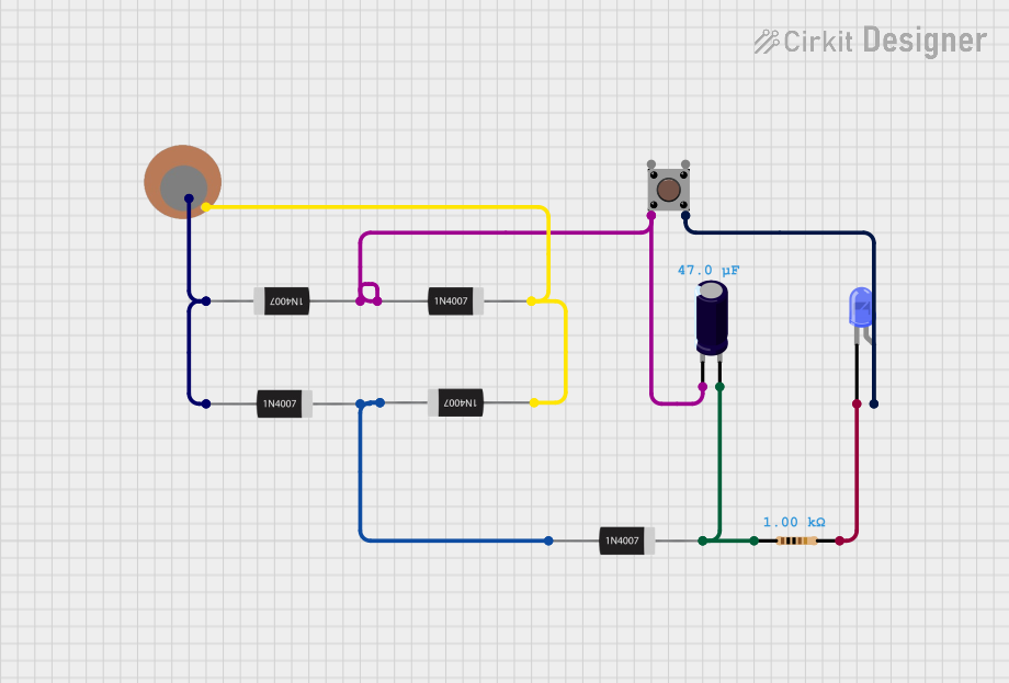
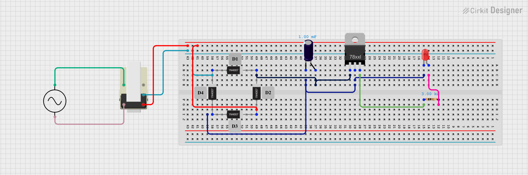
  • Filtering: To smooth out the DC output, it is common to connect a capacitor across the DC output pins. The value of the capacitor depends on the load and the desired ripple voltage.

  • Fusing: Always use a fuse on the AC input to protect against overcurrent conditions.

  • Isolation: Ensure that the rectifier is properly isolated from any conductive surfaces if it is not in a plastic package.

Troubleshooting and FAQs

Common Issues

  • Excessive Heat: If the rectifier is running hot, ensure that the current is within the specified limit and that adequate heat sinking is provided.

  • Unexpected Voltage Drops: Check for proper connections and ensure that the input voltage is within the specified range.

  • No DC Output: Verify that the AC input is connected correctly and that the rectifier is not damaged.

Solutions and Tips for Troubleshooting

  • Check Connections: Loose connections can cause a variety of issues. Ensure all connections are secure.

  • Test with Multimeter: Use a multimeter to check the voltage across the AC inputs and the DC outputs to ensure proper operation.

  • Replace if Faulty: If the rectifier is not functioning as expected and all other components in the circuit are working correctly, replace the rectifier.

FAQs

Q: Can I use the 1N4007 bridge rectifier for a circuit that requires less than 1000V? A: Yes, the 1N4007 can be used for voltages below its maximum rated voltage.

Q: What is the maximum current the 1N4007 can handle? A: The 1N4007 can handle a continuous forward current of 1A.

Q: How do I know if I need a heat sink for my application? A: If the rectifier is expected to handle currents near its rating or if it operates in a high ambient temperature, a heat sink is recommended.

Q: Can I connect this directly to an Arduino UNO? A: The rectifier can be used to provide a DC voltage to an Arduino UNO, but ensure that the output voltage is regulated to a level that is within the operating range of the Arduino (typically 5V or 3.3V).

Example Arduino UNO Connection

// No specific code is required for the bridge rectifier itself.
// The following example assumes you have a regulated 5V DC output from the rectifier.

void setup() {
  pinMode(LED_BUILTIN, OUTPUT); // Set the built-in LED as an output
}

void loop() {
  digitalWrite(LED_BUILTIN, HIGH); // Turn the LED on
  delay(1000);                     // Wait for a second
  digitalWrite(LED_BUILTIN, LOW);  // Turn the LED off
  delay(1000);                     // Wait for a second
}

Note: The above code is a simple blink program to demonstrate the use of a rectified and regulated DC power supply from the 1N4007 bridge rectifier to power an Arduino UNO. The rectifier itself does not interface with the Arduino's digital or analog pins.