
How to Use Adafruit CH552 QT Py: Examples, Pinouts, and Specs
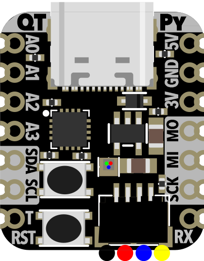
 Design with Adafruit CH552 QT Py in Cirkit Designer
Introduction
The Adafruit CH552 QT Py (Manufacturer Part ID: 5960) is a compact and versatile microcontroller board featuring the CH552 chip. Designed for ease of use and integration, this board is ideal for rapid prototyping, IoT applications, and projects requiring a small form factor. Its compatibility with various sensors and peripherals makes it a popular choice for hobbyists and professionals alike.
Explore Projects Built with Adafruit CH552 QT Py
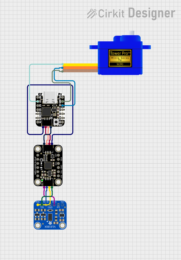 Open Project in Cirkit Designer
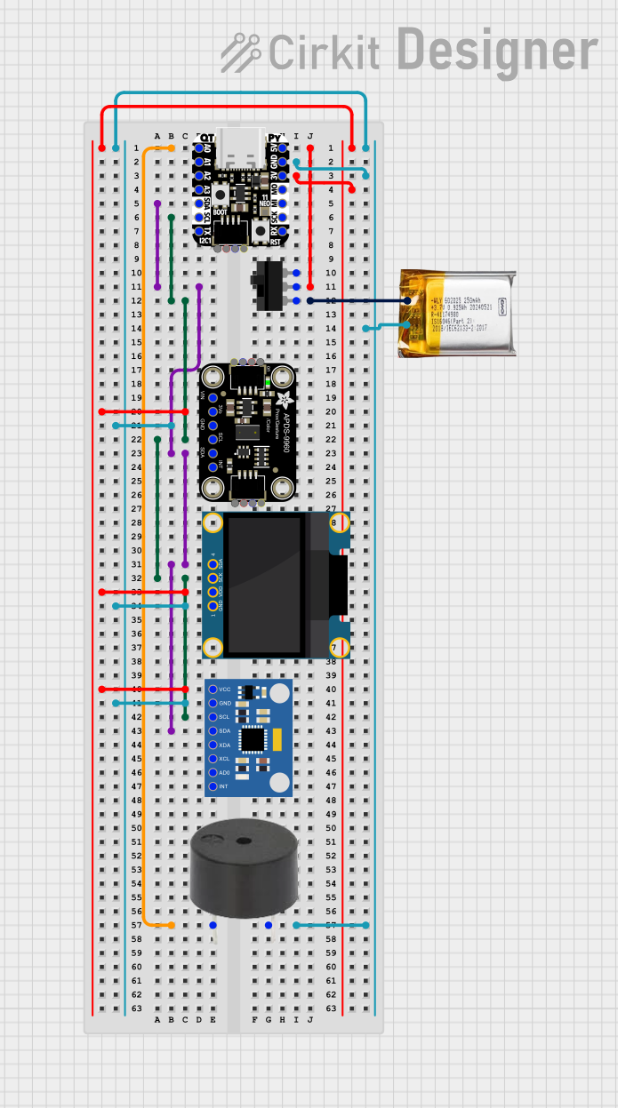 Open Project in Cirkit Designer
 Open Project in Cirkit Designer
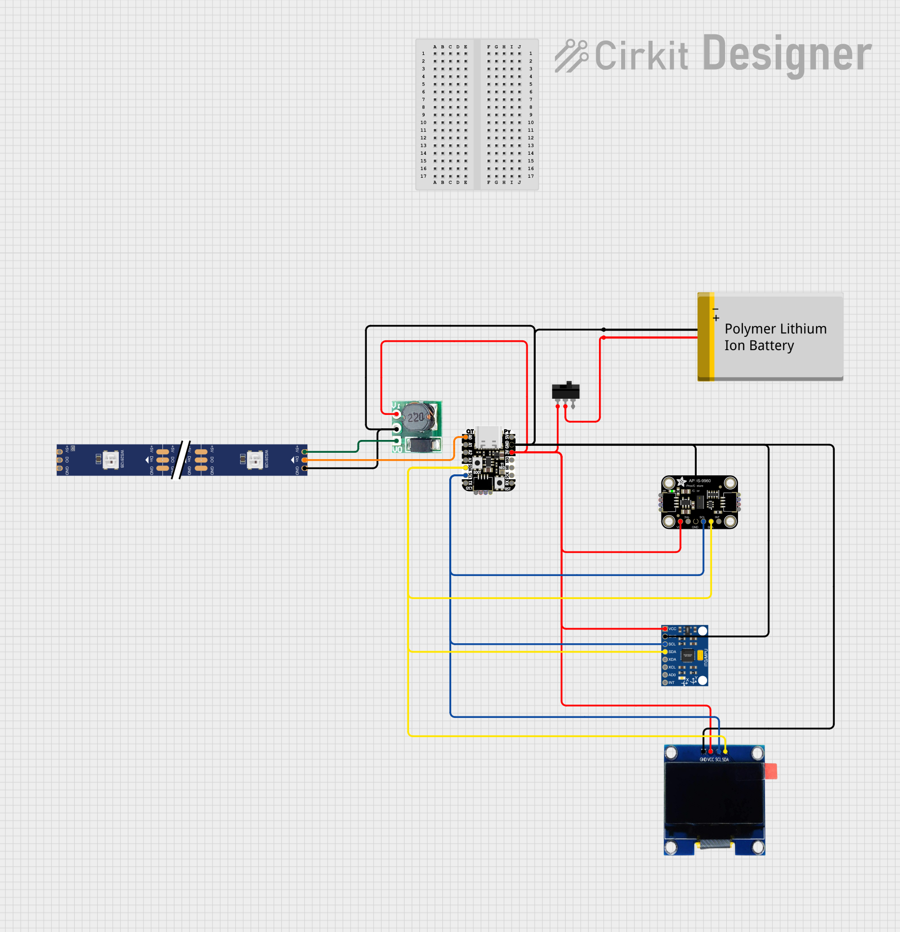 Open Project in Cirkit Designer
Explore Projects Built with Adafruit CH552 QT Py
Open Project in Cirkit DesignerOpen Project in Cirkit DesignerOpen Project in Cirkit DesignerOpen Project in Cirkit DesignerCommon Applications and Use Cases
- IoT devices and smart home projects
- Wearable electronics
- Rapid prototyping for embedded systems
- Sensor data acquisition and processing
- USB-based applications (e.g., HID devices, serial communication)
Technical Specifications
The Adafruit CH552 QT Py is built around the CH552 microcontroller, which is based on an 8-bit 8051 core. Below are the key technical details:
Key Specifications
| Parameter | Value |
|---|---|
| Microcontroller | CH552 (8051-based) |
| Operating Voltage | 3.3V |
| Input Voltage (USB) | 5V |
| Flash Memory | 16 KB |
| RAM | 1 KB |
| Clock Speed | 24 MHz |
| USB Support | USB 2.0 Full-Speed |
| GPIO Pins | 11 |
| Communication Protocols | I2C, SPI, UART |
| Dimensions | 22.8 mm x 17.8 mm |
Pin Configuration and Descriptions
The Adafruit CH552 QT Py features a total of 14 pins, including power, GPIO, and communication pins. Below is the pinout description:
| Pin Name | Pin Type | Description |
|---|---|---|
| 3V3 | Power | 3.3V output for powering external components |
| GND | Power | Ground connection |
| D0 | GPIO, UART TX | General-purpose I/O or UART transmit |
| D1 | GPIO, UART RX | General-purpose I/O or UART receive |
| D2 | GPIO | General-purpose I/O |
| D3 | GPIO, PWM | General-purpose I/O or PWM output |
| D4 | GPIO | General-purpose I/O |
| D5 | GPIO, PWM | General-purpose I/O or PWM output |
| D6 | GPIO | General-purpose I/O |
| D7 | GPIO | General-purpose I/O |
| SCL | I2C Clock | I2C clock line |
| SDA | I2C Data | I2C data line |
| MISO | SPI Input | SPI Master-In-Slave-Out |
| MOSI | SPI Output | SPI Master-Out-Slave-In |
| SCK | SPI Clock | SPI clock line |
Usage Instructions
How to Use the Adafruit CH552 QT Py in a Circuit
Powering the Board:
- Connect the board to a USB port (5V) for power and programming.
- Alternatively, use the 3V3 pin to supply 3.3V directly.
Connecting Peripherals:
- Use the GPIO pins to connect sensors, actuators, or other peripherals.
- For I2C devices, connect to the SDA and SCL pins.
- For SPI devices, connect to the MISO, MOSI, and SCK pins.
Programming the Board:
- The CH552 QT Py can be programmed using the Arduino IDE or other compatible tools.
- Install the necessary CH552 board support package (BSP) in the Arduino IDE.
Important Considerations and Best Practices
- Ensure that the input voltage does not exceed the rated 3.3V on the GPIO pins.
- Use appropriate pull-up resistors for I2C communication if required by your peripherals.
- Avoid drawing excessive current from the 3V3 pin to prevent damage to the board.
Example Code for Arduino UNO Integration
Below is an example of how to use the Adafruit CH552 QT Py with an I2C temperature sensor:
#include <Wire.h> // Include the Wire library for I2C communication

#define SENSOR_ADDR 0x48 // I2C address of the temperature sensor

void setup() {
  Wire.begin(); // Initialize I2C communication
  Serial.begin(9600); // Start serial communication for debugging
  Serial.println("CH552 QT Py I2C Example");
}

void loop() {
  Wire.beginTransmission(SENSOR_ADDR); // Start communication with the sensor
  Wire.write(0x00); // Request temperature data (register 0x00)
  Wire.endTransmission();

  Wire.requestFrom(SENSOR_ADDR, 2); // Request 2 bytes of data from the sensor
  if (Wire.available() == 2) { // Check if 2 bytes are available
    int temp = Wire.read() << 8 | Wire.read(); // Combine the two bytes
    Serial.print("Temperature: ");
    Serial.println(temp / 256.0); // Convert and print the temperature
  }

  delay(1000); // Wait 1 second before the next reading
}
Troubleshooting and FAQs
Common Issues and Solutions
The board is not recognized by the computer:
- Ensure the USB cable is functional and supports data transfer.
- Check if the correct drivers for the CH552 are installed on your computer.
Unable to upload code to the board:
- Verify that the correct board and port are selected in the Arduino IDE.
- Ensure the CH552 board support package is installed.
I2C or SPI communication is not working:
- Double-check the wiring and ensure the correct pins are used.
- Verify that the peripheral device's address or configuration matches the code.
The board overheats or malfunctions:
- Ensure that the input voltage does not exceed the rated limits.
- Avoid drawing excessive current from the GPIO or power pins.
FAQs
Q: Can the CH552 QT Py be powered by a battery?
A: Yes, you can power the board using a 3.3V battery connected to the 3V3 pin. Ensure proper voltage regulation.
Q: Is the CH552 QT Py compatible with Arduino libraries?
A: Yes, many Arduino libraries are compatible with the CH552 QT Py, but some may require minor modifications.
Q: Can I use the CH552 QT Py for USB HID applications?
A: Yes, the CH552 supports USB HID functionality, making it suitable for creating custom keyboards, mice, or other USB devices.
Q: What is the maximum current output of the 3V3 pin?
A: The 3V3 pin can supply up to 100 mA, but it is recommended to keep the current draw below this limit for stable operation.