
How to Use Screw terminal - 2 pins: Examples, Pinouts, and Specs
 Design with Screw terminal - 2 pins in Cirkit Designer
Introduction
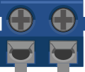
A screw terminal with two pins is a simple yet effective component used for securely connecting wires in electronic circuits. It features two screws that tighten onto the inserted wires, ensuring a reliable and stable electrical connection. This component is widely used in prototyping, industrial control systems, and DIY electronics projects due to its ease of use and durability.
Explore Projects Built with Screw terminal - 2 pins
 Open Project in Cirkit Designer
 Open Project in Cirkit Designer
 Open Project in Cirkit Designer
 Open Project in Cirkit Designer
Explore Projects Built with Screw terminal - 2 pins
Open Project in Cirkit DesignerOpen Project in Cirkit DesignerOpen Project in Cirkit DesignerOpen Project in Cirkit DesignerCommon Applications and Use Cases
- Connecting power supply wires to circuit boards
- Interfacing external devices or sensors with microcontrollers
- Industrial control systems and automation
- Prototyping and testing circuits
- Securely connecting wires in high-vibration environments
Technical Specifications
Below are the key technical details for a standard 2-pin screw terminal:
| Parameter | Value |
|---|---|
| Number of Pins | 2 |
| Rated Voltage | 300V AC/DC |
| Rated Current | 10A |
| Wire Gauge Support | 26 AWG to 12 AWG |
| Pitch (Pin Spacing) | 5.08 mm (standard) |
| Material | Plastic housing (flame-retardant) |
| Contact Material | Copper alloy with tin plating |
| Operating Temperature | -40°C to +105°C |
Pin Configuration and Descriptions
| Pin Number | Description |
|---|---|
| 1 | Terminal for wire connection (positive) |
| 2 | Terminal for wire connection (negative) |
Usage Instructions
How to Use the Component in a Circuit
- Prepare the Wires: Strip the insulation from the ends of the wires you want to connect, exposing about 5-7 mm of the conductor.
- Insert the Wires: Loosen the screws on the terminal using a small flathead screwdriver. Insert the stripped wire ends into the terminal openings.
- Tighten the Screws: Securely tighten the screws to clamp the wires in place. Ensure the wires are firmly held and do not move.
- Connect to Circuit: Solder the pins of the screw terminal to the PCB or insert them into a breadboard for prototyping.
Important Considerations and Best Practices
- Wire Gauge Compatibility: Ensure the wire gauge matches the terminal's supported range (26 AWG to 12 AWG).
- Avoid Over-Tightening: Tighten the screws just enough to secure the wires. Over-tightening can damage the wires or the terminal.
- Check Connections: After installation, gently tug on the wires to confirm they are securely clamped.
- Polarity Awareness: If used in a polarized circuit, ensure the correct wire is connected to the appropriate terminal.
- Soldering: When soldering the pins to a PCB, use a soldering iron with a temperature of 350°C to 400°C for optimal results.
Example: Connecting to an Arduino UNO
The screw terminal can be used to connect external devices, such as motors or sensors, to an Arduino UNO. Below is an example of connecting a 12V DC motor to an Arduino using a screw terminal and an external power supply.
Circuit Diagram
- Connect the positive wire of the motor to one terminal of the screw terminal.
- Connect the negative wire of the motor to the other terminal.
- Use a motor driver (e.g., L298N) to interface the motor with the Arduino.
Arduino Code Example
// Example code to control a DC motor using Arduino and a screw terminal
// connected to a motor driver (e.g., L298N).

const int motorPin = 9; // PWM pin connected to the motor driver

void setup() {
  pinMode(motorPin, OUTPUT); // Set motor pin as output
}

void loop() {
  analogWrite(motorPin, 128); // Run motor at 50% speed
  delay(2000);               // Keep motor running for 2 seconds

  analogWrite(motorPin, 0);  // Stop the motor
  delay(2000);               // Wait for 2 seconds before restarting
}
Troubleshooting and FAQs
Common Issues Users Might Face
- Loose Connections: If the wires are not securely clamped, the connection may be intermittent or fail.
- Solution: Ensure the screws are tightened properly and the wires are fully inserted.
- Wire Slippage: Thin wires may slip out of the terminal if not clamped correctly.
- Solution: Use thicker wires within the supported gauge range or twist the wire strands before inserting.
- Overheating: Excessive current can cause the terminal to overheat.
- Solution: Ensure the current does not exceed the rated 10A limit.
- Damaged Screws or Threads: Over-tightening can strip the threads or damage the screws.
- Solution: Tighten screws gently and avoid using excessive force.
FAQs
Q: Can I use this screw terminal for AC connections?
A: Yes, the terminal is rated for up to 300V AC, making it suitable for low-voltage AC applications.
Q: Is the terminal reusable?
A: Yes, the terminal can be reused multiple times as long as the screws and housing remain intact.
Q: Can I use stranded wires with this terminal?
A: Yes, stranded wires are compatible. For best results, twist the strands before inserting them into the terminal.
Q: What tools do I need to use this component?
A: A small flathead screwdriver is required to tighten or loosen the screws. Wire strippers may also be needed to prepare the wires.
By following these guidelines, you can effectively use the 2-pin screw terminal in your electronic projects!