How to Use A6: Examples, Pinouts, and Specs
Introduction
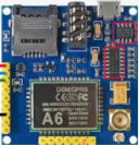
The A6 module, manufactured by AI Thinker, is a GSM/GPRS integrated circuit designed for wireless communication. It is widely used in applications requiring mobile network connectivity, such as IoT devices, remote monitoring systems, and smart home automation. The A6 module supports voice, SMS, and data transmission over GSM networks, making it a versatile choice for embedded systems.
Explore Projects Built with A6


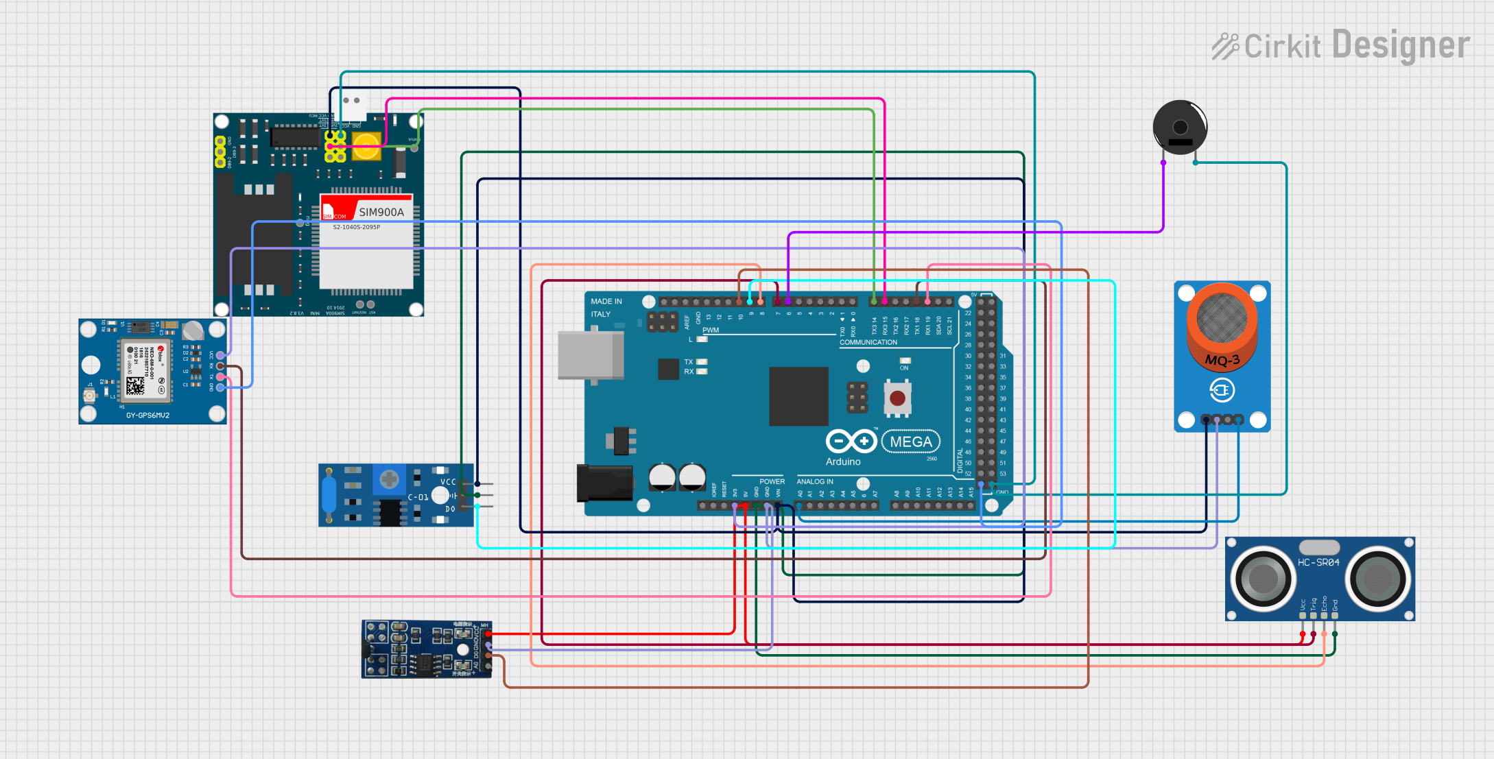
Explore Projects Built with A6
Common Applications and Use Cases
- Internet of Things (IoT) devices
- Remote monitoring and control systems
- Smart home automation
- GPS tracking systems
- SMS-based alert systems
- Wireless data transmission in industrial applications
Technical Specifications
The A6 GSM/GPRS module is designed to operate efficiently in a variety of environments. Below are its key technical specifications:
General Specifications
| Parameter | Value |
|---|---|
| Manufacturer | AI Thinker |
| Part ID | GSM/GPRS |
| Operating Voltage | 3.3V to 4.2V |
| Operating Current | 1.5mA (idle), ~2A (peak) |
| Frequency Bands | GSM 850/900/1800/1900 MHz |
| Data Transmission | GPRS Class 10, TCP/IP support |
| Communication Protocols | UART, AT Commands |
| Operating Temperature | -40°C to +85°C |
| Dimensions | 22.8mm x 16.8mm x 2.5mm |
Pin Configuration and Descriptions
The A6 module has a total of 24 pins. Below is the pin configuration and their respective functions:
| Pin Number | Pin Name | Description |
|---|---|---|
| 1 | VCC | Power supply input (3.3V to 4.2V) |
| 2 | GND | Ground connection |
| 3 | TXD | UART Transmit Data (connect to RX of MCU) |
| 4 | RXD | UART Receive Data (connect to TX of MCU) |
| 5 | RST | Reset pin (active low) |
| 6 | NET | Network status indicator (blinks for status) |
| 7 | MIC+ | Microphone positive input |
| 8 | MIC- | Microphone negative input |
| 9 | SPK+ | Speaker positive output |
| 10 | SPK- | Speaker negative output |
| 11-24 | NC | Not connected |
Usage Instructions
The A6 GSM/GPRS module is straightforward to use in embedded systems. Below are the steps and best practices for integrating it into your project:
Connecting the A6 Module
- Power Supply: Connect the VCC pin to a stable 3.3V to 4.2V power source. Ensure the power supply can handle peak currents of up to 2A.
- UART Communication: Connect the TXD and RXD pins to the RX and TX pins of your microcontroller, respectively. Use a logic level converter if your microcontroller operates at 5V logic.
- Antenna: Attach a GSM antenna to the module for proper signal reception.
- Reset: Connect the RST pin to a GPIO pin of your microcontroller for manual or software-controlled resets.
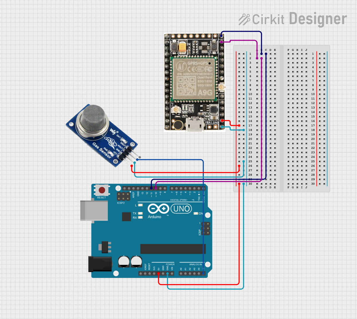
Example: Using A6 with Arduino UNO
Below is an example of how to use the A6 module with an Arduino UNO to send an SMS:
Circuit Connections
- Connect A6
VCCto a 3.7V power source. - Connect A6
GNDto ArduinoGND. - Connect A6
TXDto ArduinoRX(pin 0). - Connect A6
RXDto ArduinoTX(pin 1). - Connect an antenna to the A6 module.
Arduino Code
#include <SoftwareSerial.h>

// Define RX and TX pins for SoftwareSerial
SoftwareSerial A6Serial(10, 11); // RX = pin 10, TX = pin 11

void setup() {
  // Initialize serial communication with the A6 module
  A6Serial.begin(9600); // A6 default baud rate is 9600
  Serial.begin(9600);   // For debugging via Serial Monitor

  // Wait for the module to initialize
  delay(5000);
  Serial.println("Initializing A6 module...");

  // Send an SMS
  sendSMS("+1234567890", "Hello from A6 module!");
}

void loop() {
  // Continuously check for incoming data from the A6 module
  if (A6Serial.available()) {
    Serial.write(A6Serial.read());
  }
}

void sendSMS(String phoneNumber, String message) {
  A6Serial.println("AT+CMGF=1"); // Set SMS mode to text
  delay(1000);

  A6Serial.print("AT+CMGS=\"");
  A6Serial.print(phoneNumber);
  A6Serial.println("\"");
  delay(1000);

  A6Serial.print(message); // Send the SMS message
  delay(1000);

  A6Serial.write(26); // Send Ctrl+Z to indicate end of message
  delay(5000);

  Serial.println("SMS sent!");
}
Best Practices
- Use a decoupling capacitor (e.g., 100µF) near the VCC pin to stabilize the power supply.
- Ensure the antenna is securely connected for optimal signal strength.
- Avoid using the module in areas with poor GSM network coverage.
Troubleshooting and FAQs
Common Issues and Solutions
Module Not Responding to AT Commands
- Ensure the module is powered correctly and the UART connections are secure.
- Check the baud rate (default is 9600) and adjust if necessary.
Poor Signal Strength
- Verify that the antenna is properly connected.
- Test the module in an area with better GSM network coverage.
SMS Not Sending
- Confirm that the SIM card is active and has sufficient balance.
- Ensure the SIM card is inserted correctly and the module is registered on the network.
Frequent Resets
- Check the power supply for stability. Use a power source capable of handling peak currents.
FAQs
Q: Can the A6 module be used for voice calls?
A: Yes, the A6 module supports voice calls. Connect a microphone and speaker to the respective pins for audio input and output.
Q: What is the maximum data rate supported by the A6 module?
A: The A6 module supports GPRS Class 10, with a maximum data rate of 85.6 kbps.
Q: Does the A6 module support 3G or 4G networks?
A: No, the A6 module only supports GSM (2G) networks.
Q: How can I update the firmware of the A6 module?
A: Firmware updates can be performed via the UART interface using the manufacturer's tools and instructions.
By following this documentation, you can effectively integrate and troubleshoot the A6 GSM/GPRS module in your projects.