How to Use Camera (OV7670 – 5MP): Examples, Pinouts, and Specs
Introduction
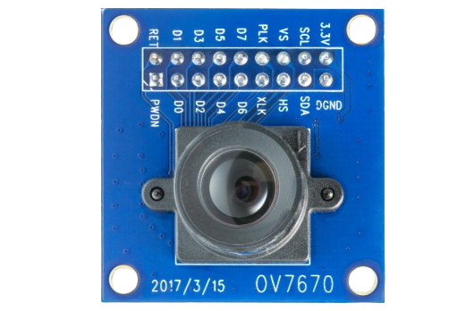
The OV7670 is a low-cost, high-performance image sensor designed for capturing 5-megapixel images. Manufactured by Ardino with the part ID "UNO," this camera module is compact and versatile, making it ideal for embedded systems, robotics, IoT devices, and other applications requiring image capture and processing. The OV7670 supports multiple output formats and includes built-in image processing features such as color correction, gamma adjustment, and white balance.
Explore Projects Built with Camera (OV7670 – 5MP)
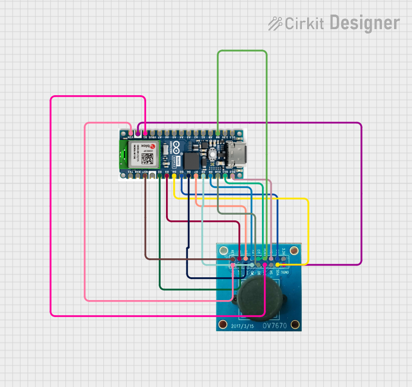
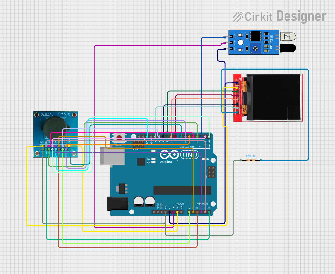
Explore Projects Built with Camera (OV7670 – 5MP)
Common Applications:
- Robotics: Object detection and navigation
- IoT Devices: Remote monitoring and surveillance
- Embedded Systems: Image capture and processing
- Machine Vision: Pattern recognition and tracking
- DIY Projects: Photography and video recording
Technical Specifications
Key Technical Details:
| Parameter | Value |
|---|---|
| Manufacturer | Ardino |
| Part ID | UNO |
| Image Resolution | 5 Megapixels |
| Output Formats | RGB565, YUV422, YCbCr |
| Operating Voltage | 3.3V (I/O), 2.5V (Core) |
| Power Consumption | ~60mW |
| Frame Rate | Up to 30 fps (QVGA) |
| Lens Type | Fixed focus |
| Interface | SCCB (Serial Camera Control Bus) |
| Operating Temperature | -30°C to 70°C |
| Dimensions | 24mm x 24mm |
Pin Configuration and Descriptions:
The OV7670 module has a 10-pin interface for communication and power. Below is the pinout:
| Pin Number | Pin Name | Description |
|---|---|---|
| 1 | GND | Ground |
| 2 | VCC | Power supply (3.3V) |
| 3 | SCL | SCCB clock line (I2C-compatible) |
| 4 | SDA | SCCB data line (I2C-compatible) |
| 5 | VSYNC | Vertical synchronization signal |
| 6 | HREF | Horizontal reference signal |
| 7 | PCLK | Pixel clock output |
| 8 | XCLK | External clock input (12 MHz recommended) |
| 9 | D0-D7 | Data bus (8-bit parallel output) |
| 10 | RESET | Active-low reset signal |
Usage Instructions
How to Use the OV7670 in a Circuit:
- Power Supply: Connect the VCC pin to a 3.3V power source and GND to ground.
- Clock Signal: Provide a 12 MHz clock signal to the XCLK pin using an external oscillator or microcontroller.
- Communication: Use the SCCB interface (SCL and SDA pins) to configure the camera settings such as resolution, frame rate, and output format.
- Data Output: Connect the D0-D7 pins to a microcontroller or FPGA to receive image data. Use the PCLK, VSYNC, and HREF signals for synchronization.
- Reset: Use the RESET pin to initialize the camera module.
Important Considerations:
- Voltage Levels: Ensure all I/O pins operate at 3.3V logic levels. Use level shifters if interfacing with 5V systems.
- Clock Stability: A stable 12 MHz clock signal is critical for proper operation.
- Decoupling Capacitors: Place decoupling capacitors near the VCC pin to reduce noise.
- Lens Adjustment: The fixed-focus lens may require manual adjustment for optimal image clarity.
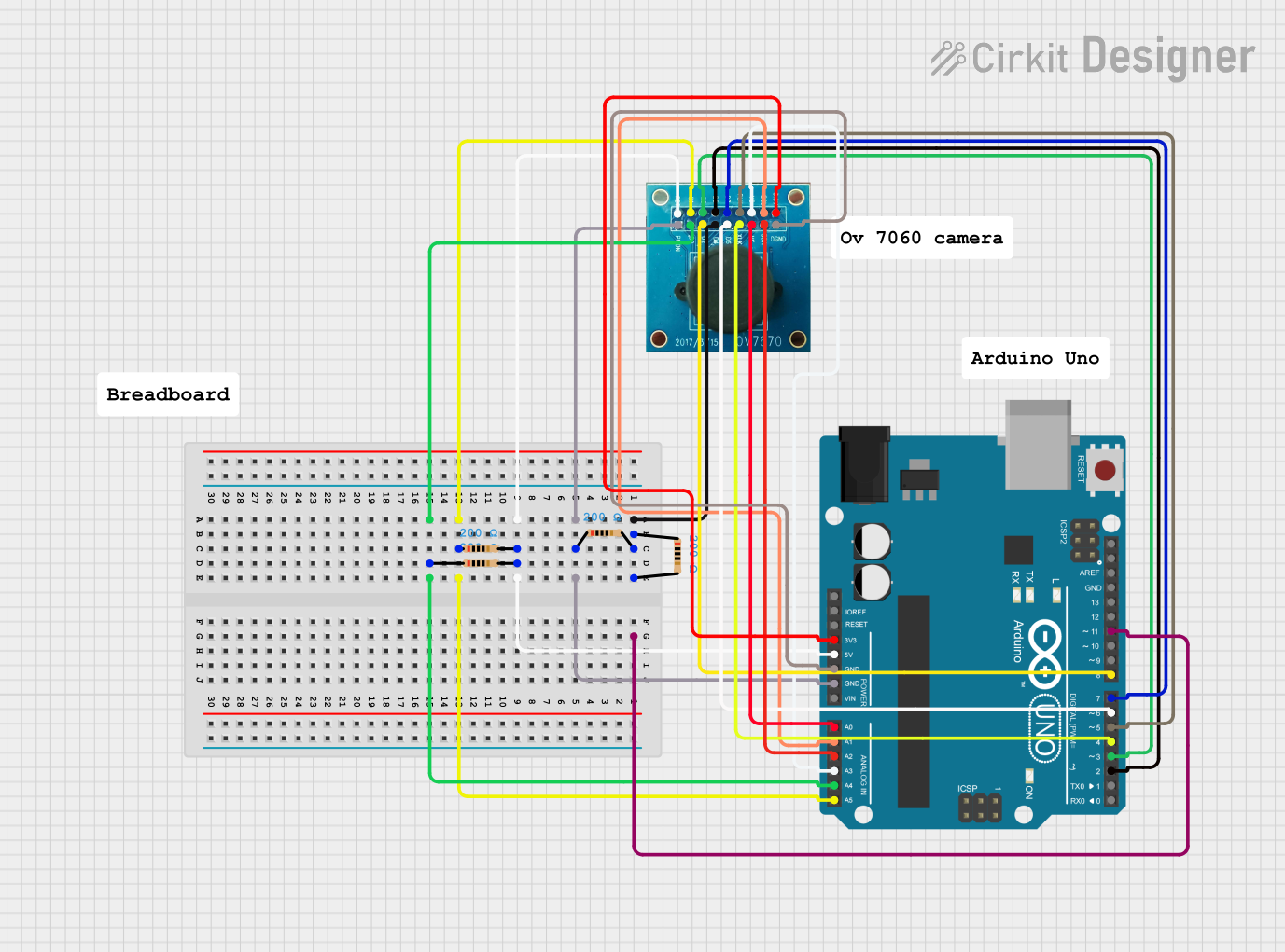
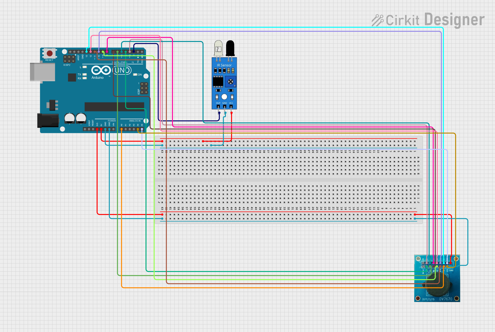
Example: Connecting OV7670 to Arduino UNO
Below is an example of interfacing the OV7670 with an Arduino UNO for basic image capture:
Wiring Diagram:
| OV7670 Pin | Arduino UNO Pin |
|---|---|
| GND | GND |
| VCC | 3.3V |
| SCL | A5 (I2C Clock) |
| SDA | A4 (I2C Data) |
| VSYNC | Digital Pin 2 |
| HREF | Digital Pin 3 |
| PCLK | Digital Pin 4 |
| XCLK | Digital Pin 9 |
| D0-D7 | Digital Pins 5-12 |
Arduino Code:
#include <Wire.h> // Include the Wire library for I2C communication

// Define OV7670 SCCB address
#define OV7670_ADDRESS 0x42

void setup() {
  Wire.begin(); // Initialize I2C communication
  Serial.begin(9600); // Start serial communication for debugging

  // Initialize the OV7670
  if (initializeCamera()) {
    Serial.println("Camera initialized successfully!");
  } else {
    Serial.println("Camera initialization failed.");
  }
}

bool initializeCamera() {
  Wire.beginTransmission(OV7670_ADDRESS);
  // Example: Write a register value to configure the camera
  Wire.write(0x12); // Register address (e.g., COM7)
  Wire.write(0x80); // Reset the camera
  if (Wire.endTransmission() == 0) {
    return true; // Success
  }
  return false; // Failure
}

void loop() {
  // Add code to capture and process image data
}
Notes:
- The above code demonstrates basic initialization. Additional configuration is required for capturing images.
- Use libraries such as
OV7670orArduCAMfor advanced functionality.
Troubleshooting and FAQs
Common Issues:
No Image Output:
- Ensure the XCLK pin is receiving a stable 12 MHz clock signal.
- Verify the SCCB communication by checking the SCL and SDA connections.
- Confirm the camera is powered with 3.3V.
Distorted or Blurry Images:
- Adjust the lens focus manually.
- Check for proper synchronization using the VSYNC and HREF signals.
Camera Not Detected:
- Verify the SCCB address (default: 0x42).
- Ensure pull-up resistors are present on the SCL and SDA lines.
Tips for Troubleshooting:
- Use an oscilloscope to monitor the clock and synchronization signals.
- Test the SCCB communication by reading and writing to camera registers.
- Refer to the OV7670 datasheet for detailed register descriptions and configuration options.
FAQs:
Q: Can the OV7670 work with 5V microcontrollers?
A: Yes, but you must use level shifters to convert 5V logic to 3.3V.
Q: What is the maximum resolution supported?
A: The OV7670 supports up to 640x480 (VGA) resolution.
Q: Can the camera capture video?
A: Yes, the OV7670 can capture video at up to 30 fps in QVGA resolution.
Q: Is there a library for Arduino?
A: Yes, libraries like ArduCAM simplify interfacing with the OV7670.
This concludes the documentation for the OV7670 camera module.