How to Use ESP32-Robo Expansion Board: Examples, Pinouts, and Specs
Introduction
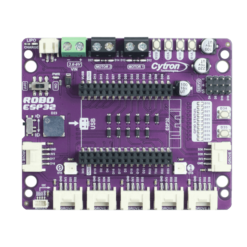
The ESP32-Robo Expansion Board (Manufacturer Part ID: ROBO-ESP32) by Cytron is a versatile expansion board designed to enhance the functionality of the ESP32 microcontroller. It provides additional interfaces and connectivity options, including motor drivers, sensor ports, and communication interfaces, making it an ideal choice for robotics and IoT projects. This board simplifies the integration of motors, sensors, and other peripherals, enabling rapid prototyping and development.
Explore Projects Built with ESP32-Robo Expansion Board
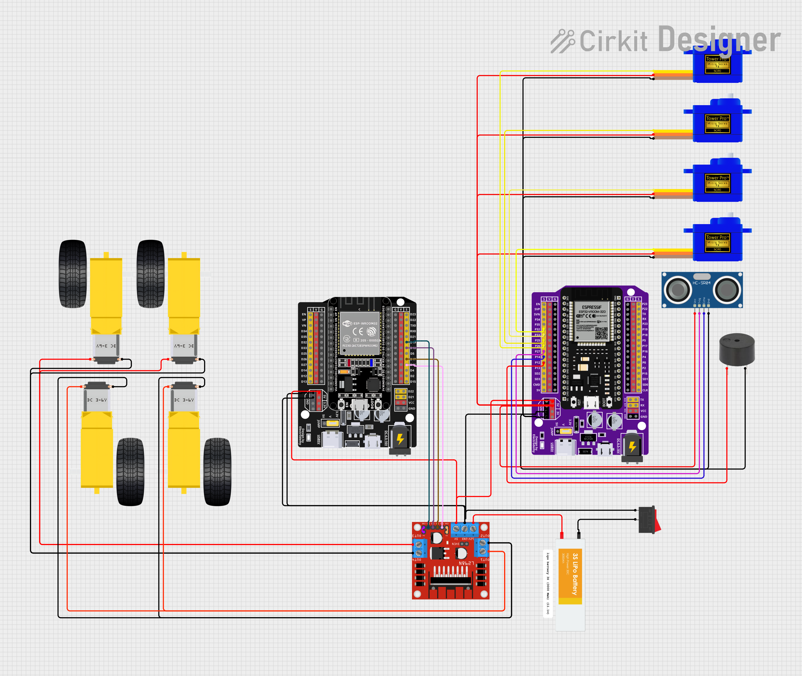


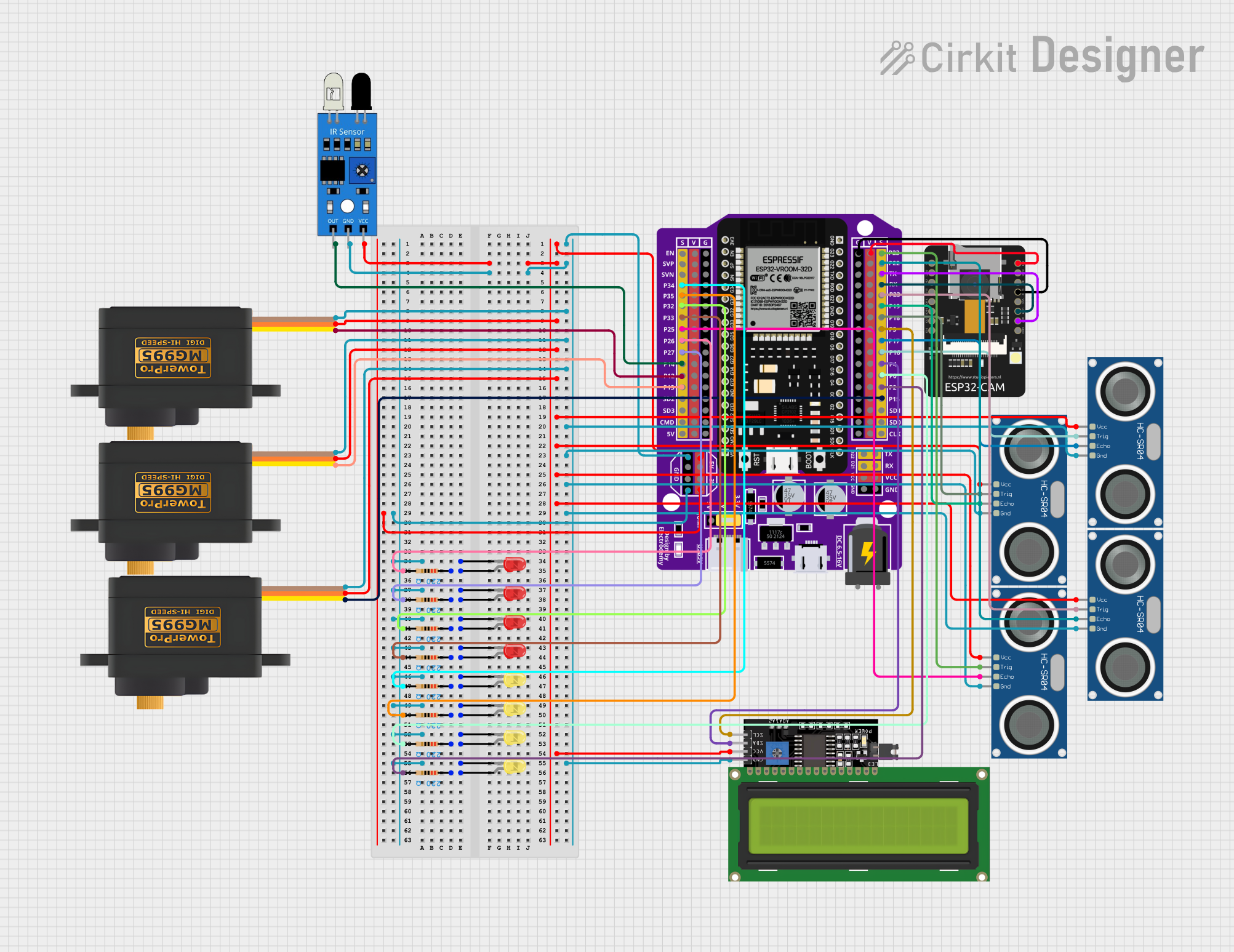
Explore Projects Built with ESP32-Robo Expansion Board
Common Applications and Use Cases
- Robotics projects requiring motor control and sensor integration
- IoT systems with multiple communication interfaces
- Educational platforms for learning embedded systems and robotics
- Prototyping autonomous vehicles or robotic arms
- Smart home automation projects
Technical Specifications
The ESP32-Robo Expansion Board is designed to work seamlessly with the ESP32 microcontroller, offering robust features for robotics and IoT applications.
Key Technical Details
| Parameter | Specification |
|---|---|
| Microcontroller Support | ESP32 |
| Motor Driver | Dual-channel DC motor driver (L298P) |
| Input Voltage Range | 7V - 12V |
| Motor Output Current | Up to 2A per channel |
| Communication Interfaces | UART, I2C, SPI |
| Sensor Ports | 4x Analog/Digital Input Ports |
| Power Output | 5V and 3.3V regulated outputs |
| Dimensions | 90mm x 70mm x 20mm |
Pin Configuration and Descriptions
The ESP32-Robo Expansion Board features a variety of pins and connectors for interfacing with peripherals. Below is the pin configuration:
Motor Driver Pins
| Pin Name | Description |
|---|---|
| M1A | Motor 1 Output A |
| M1B | Motor 1 Output B |
| M2A | Motor 2 Output A |
| M2B | Motor 2 Output B |
| ENA | Motor 1 Enable (PWM control) |
| ENB | Motor 2 Enable (PWM control) |
Sensor Ports
| Pin Name | Description |
|---|---|
| S1 | Sensor Port 1 (Analog/Digital Input) |
| S2 | Sensor Port 2 (Analog/Digital Input) |
| S3 | Sensor Port 3 (Analog/Digital Input) |
| S4 | Sensor Port 4 (Analog/Digital Input) |
Power and Communication Pins
| Pin Name | Description |
|---|---|
| VIN | Input Voltage (7V - 12V) |
| GND | Ground |
| 5V | 5V Regulated Output |
| 3.3V | 3.3V Regulated Output |
| TXD | UART Transmit |
| RXD | UART Receive |
| SCL | I2C Clock Line |
| SDA | I2C Data Line |
Usage Instructions
The ESP32-Robo Expansion Board is designed for easy integration with the ESP32 microcontroller. Follow the steps below to use the board effectively:
Connecting the ESP32
- Mount the ESP32 microcontroller onto the expansion board's headers.
- Ensure proper alignment of the pins to avoid damage.
Powering the Board
- Connect a DC power supply (7V - 12V) to the VIN and GND terminals.
- The onboard voltage regulators will provide 5V and 3.3V outputs for peripherals.
Controlling Motors
- Connect DC motors to the M1A/M1B and M2A/M2B terminals.
- Use the ENA and ENB pins for PWM-based speed control.
- Below is an example Arduino sketch for controlling the motors:
// Example code to control motors using ESP32-Robo Expansion Board
#define ENA 25  // Motor 1 Enable pin
#define ENB 26  // Motor 2 Enable pin
#define M1A 27  // Motor 1 Output A
#define M1B 14  // Motor 1 Output B
#define M2A 12  // Motor 2 Output A
#define M2B 13  // Motor 2 Output B

void setup() {
  // Set motor control pins as outputs
  pinMode(ENA, OUTPUT);
  pinMode(ENB, OUTPUT);
  pinMode(M1A, OUTPUT);
  pinMode(M1B, OUTPUT);
  pinMode(M2A, OUTPUT);
  pinMode(M2B, OUTPUT);
}

void loop() {
  // Example: Rotate Motor 1 forward
  digitalWrite(M1A, HIGH);
  digitalWrite(M1B, LOW);
  analogWrite(ENA, 128);  // Set speed (0-255)

  // Example: Rotate Motor 2 backward
  digitalWrite(M2A, LOW);
  digitalWrite(M2B, HIGH);
  analogWrite(ENB, 200);  // Set speed (0-255)

  delay(2000);  // Run motors for 2 seconds

  // Stop both motors
  analogWrite(ENA, 0);
  analogWrite(ENB, 0);

  delay(2000);  // Wait for 2 seconds
}
Connecting Sensors
- Attach sensors to the S1-S4 ports.
- Use the corresponding analog or digital pins in your code to read sensor data.
Important Considerations
- Ensure the input voltage does not exceed 12V to avoid damaging the board.
- Use appropriate heat sinks or cooling mechanisms if driving motors at high currents.
- Double-check all connections before powering the board.
Troubleshooting and FAQs
Common Issues and Solutions
Motors not running:
- Verify the motor connections to M1A/M1B and M2A/M2B.
- Check the ENA and ENB PWM signals in your code.
- Ensure the power supply provides sufficient current for the motors.
Sensors not responding:
- Confirm the sensor connections to the S1-S4 ports.
- Check the sensor's operating voltage and ensure compatibility with the board.
ESP32 not powering on:
- Verify the VIN and GND connections.
- Ensure the input voltage is within the 7V - 12V range.
Overheating motor driver:
- Reduce the motor load or use a cooling mechanism.
- Check for short circuits in the motor wiring.
FAQs
Can I use stepper motors with this board?
- No, the onboard L298P motor driver is designed for DC motors only.
What is the maximum current the board can handle?
- The motor driver can handle up to 2A per channel.
Is the board compatible with other microcontrollers?
- While designed for ESP32, the board can be used with other microcontrollers that match the pinout.
Can I power the board using a USB connection?
- No, the board requires a DC power supply connected to the VIN terminal.
By following this documentation, you can effectively utilize the ESP32-Robo Expansion Board for your robotics and IoT projects.