How to Use MAX86150: Examples, Pinouts, and Specs
Introduction
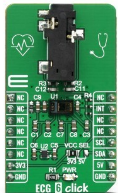
The MAX86150 is a highly integrated optical heart-rate and SpO2 sensor module designed for wearable applications. Manufactured by MIKROE (Part ID: 4061), this module combines a photodetector, two LEDs, and an analog front-end (AFE) in a compact package. It is optimized for low-power operation, making it ideal for continuous monitoring of heart rate and blood oxygen levels in portable and wearable devices.
Explore Projects Built with MAX86150


Explore Projects Built with MAX86150
Common Applications and Use Cases
- Fitness trackers and smartwatches
- Medical monitoring devices
- Health and wellness applications
- Remote patient monitoring systems
- Research and development in biosensing technologies
Technical Specifications
The MAX86150 offers robust performance and flexibility for various applications. Below are its key technical details:
Key Technical Details
- Supply Voltage: 1.8V (core) and 3.3V (I/O)
- Current Consumption: 10µA (typical in shutdown mode), 600µA (typical in active mode)
- LED Wavelengths: Red (660nm) and Infrared (880nm)
- Sampling Rate: Programmable up to 3200 samples per second
- Communication Interface: I²C (up to 400kHz)
- Operating Temperature Range: -40°C to +85°C
- Package: 3.3mm x 5.6mm x 1.3mm, 22-pin optical module
Pin Configuration and Descriptions
The MAX86150 module has 22 pins. Below is a table describing the key pins:
| Pin Name | Type | Description |
|---|---|---|
| VDD | Power | 1.8V supply voltage for the core |
| VLED | Power | 3.3V supply voltage for the LEDs |
| GND | Ground | Ground connection |
| SDA | I²C Data | Serial data line for I²C communication |
| SCL | I²C Clock | Serial clock line for I²C communication |
| INT | Output | Interrupt output for data-ready or error signaling |
| RST | Input | Active-low reset pin |
| NC | No Connection | Not connected; leave floating |
Usage Instructions
The MAX86150 is straightforward to integrate into a circuit, but proper setup is essential for optimal performance.
How to Use the Component in a Circuit
- Power Supply: Connect the VDD pin to a 1.8V regulated power source and the VLED pin to a 3.3V source. Ensure proper decoupling capacitors are placed near the power pins.
- I²C Communication: Connect the SDA and SCL pins to the corresponding I²C lines of your microcontroller. Use pull-up resistors (typically 4.7kΩ) on both lines.
- Interrupt Handling: Connect the INT pin to a GPIO pin on your microcontroller to handle interrupts for data-ready signals.
- Reset: Use the RST pin to reset the module during initialization or in case of errors.
Important Considerations and Best Practices
- Placement: Ensure the sensor is placed close to the skin for accurate readings. Avoid obstructions between the sensor and the skin.
- Ambient Light: Minimize ambient light interference by using an opaque enclosure or covering the sensor.
- I²C Address: The default I²C address of the MAX86150 is
0x5E. Ensure no address conflicts with other devices on the I²C bus. - Initialization: Configure the sensor's registers for desired sampling rates, LED currents, and other parameters before starting measurements.
Example Code for Arduino UNO
Below is an example of how to interface the MAX86150 with an Arduino UNO using the I²C protocol:
#include <Wire.h>

// MAX86150 I2C address
#define MAX86150_I2C_ADDRESS 0x5E

void setup() {
  Wire.begin(); // Initialize I2C communication
  Serial.begin(9600); // Initialize serial communication for debugging

  // Reset the MAX86150
  Wire.beginTransmission(MAX86150_I2C_ADDRESS);
  Wire.write(0x0F); // Write to the reset register
  Wire.write(0x01); // Reset command
  Wire.endTransmission();
  delay(100); // Wait for the reset to complete

  // Configure the MAX86150 (example: set LED current and sampling rate)
  Wire.beginTransmission(MAX86150_I2C_ADDRESS);
  Wire.write(0x0A); // Write to the LED configuration register
  Wire.write(0x1F); // Example configuration: set LED current
  Wire.endTransmission();

  Serial.println("MAX86150 initialized.");
}

void loop() {
  // Read data from the MAX86150
  Wire.beginTransmission(MAX86150_I2C_ADDRESS);
  Wire.write(0x07); // Address of the data register
  Wire.endTransmission(false);
  Wire.requestFrom(MAX86150_I2C_ADDRESS, 6); // Request 6 bytes of data

  if (Wire.available() == 6) {
    uint8_t data[6];
    for (int i = 0; i < 6; i++) {
      data[i] = Wire.read(); // Read each byte
    }

    // Process the data (example: print raw values)
    Serial.print("Raw Data: ");
    for (int i = 0; i < 6; i++) {
      Serial.print(data[i], HEX);
      Serial.print(" ");
    }
    Serial.println();
  }

  delay(100); // Delay between readings
}
Troubleshooting and FAQs
Common Issues and Solutions
No Data Output:
- Cause: Incorrect I²C address or wiring.
- Solution: Verify the I²C address and ensure proper connections for SDA and SCL.
Inaccurate Readings:
- Cause: Poor sensor placement or ambient light interference.
- Solution: Ensure the sensor is in direct contact with the skin and shield it from ambient light.
Module Not Responding:
- Cause: Improper power supply or reset configuration.
- Solution: Check the power supply voltages and ensure the RST pin is properly handled.
I²C Communication Errors:
- Cause: Missing pull-up resistors or incorrect clock speed.
- Solution: Add 4.7kΩ pull-up resistors to SDA and SCL lines and ensure the clock speed is within the module's specifications.
FAQs
Q1: Can the MAX86150 be used for continuous monitoring?
Yes, the MAX86150 is designed for continuous monitoring with low power consumption, making it suitable for wearable devices.
Q2: What is the maximum sampling rate?
The MAX86150 supports a programmable sampling rate of up to 3200 samples per second.
Q3: How do I reduce power consumption?
Use the shutdown mode when the sensor is not in use. This reduces current consumption to approximately 10µA.
Q4: Can I use the MAX86150 with a 5V microcontroller?
Yes, but you must use level shifters for the I²C lines, as the MAX86150 operates at 1.8V and 3.3V logic levels.
This concludes the documentation for the MAX86150. For further details, refer to the manufacturer's datasheet.