How to Use GLYPHSENSE-ICS43434-2CH: Examples, Pinouts, and Specs
Introduction
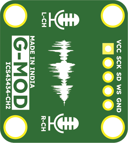
The GLYPHSENSE-ICS43434-2CH (Manufacturer Part ID: GS-004) is a high-performance, low-noise microphone array integrated circuit designed by PCBCUPID. This component features two channels for stereo sound capture and advanced signal processing capabilities, making it ideal for applications requiring high-quality audio input.
Explore Projects Built with GLYPHSENSE-ICS43434-2CH


Explore Projects Built with GLYPHSENSE-ICS43434-2CH
Common Applications and Use Cases
- Voice recognition systems
- Smart home devices (e.g., smart speakers, voice assistants)
- Audio recording equipment
- Noise-canceling systems
- IoT devices with audio input capabilities
Technical Specifications
The following table outlines the key technical details of the GLYPHSENSE-ICS43434-2CH:
| Parameter | Value |
|---|---|
| Supply Voltage (VDD) | 1.8V to 3.3V |
| Operating Current | 1.5 mA (typical) |
| Signal-to-Noise Ratio | 65 dB |
| Frequency Response | 20 Hz to 20 kHz |
| Output Format | Pulse Density Modulation (PDM) |
| Number of Channels | 2 (Stereo) |
| Operating Temperature | -40°C to +85°C |
| Package Type | LGA-10 (3.5 mm x 2.65 mm x 0.98 mm) |
Pin Configuration and Descriptions
The GLYPHSENSE-ICS43434-2CH has a 10-pin LGA package. The pin configuration is as follows:
| Pin Number | Pin Name | Description |
|---|---|---|
| 1 | VDD | Power supply input (1.8V to 3.3V). |
| 2 | GND | Ground connection. |
| 3 | CLK | Clock input for PDM signal. |
| 4 | DATA | PDM data output. |
| 5 | LRSEL | Left/Right channel select. |
| 6 | NC | No connection (leave unconnected). |
| 7 | VDD | Power supply input (redundant pin). |
| 8 | GND | Ground connection (redundant pin). |
| 9 | TEST | Factory test pin (leave unconnected). |
| 10 | NC | No connection (leave unconnected). |
Usage Instructions
How to Use the Component in a Circuit
- Power Supply: Connect the VDD pin to a stable power source (1.8V to 3.3V) and the GND pin to ground.
- Clock Signal: Provide a clock signal (typically 1-3 MHz) to the CLK pin. This clock drives the PDM output.
- Data Output: Connect the DATA pin to a microcontroller or DSP capable of processing PDM signals.
- Channel Selection: Use the LRSEL pin to select the channel:
- Logic HIGH: Right channel
- Logic LOW: Left channel
- Unused Pins: Leave the NC and TEST pins unconnected.
Important Considerations and Best Practices
- Decoupling Capacitors: Place a 0.1 µF ceramic capacitor close to the VDD pin to reduce power supply noise.
- Clock Stability: Ensure the clock signal is stable and within the specified frequency range for optimal performance.
- PCB Layout: Minimize trace lengths for the CLK and DATA lines to reduce noise and signal degradation.
- Microphone Placement: For best results, position the microphone array in a location free from obstructions and away from noise sources.
Example: Connecting to an Arduino UNO
The GLYPHSENSE-ICS43434-2CH can be interfaced with an Arduino UNO for audio processing. Below is an example of how to connect and use the component:
Circuit Connections
| GLYPHSENSE Pin | Arduino Pin |
|---|---|
| VDD | 3.3V |
| GND | GND |
| CLK | D3 (PWM pin) |
| DATA | D2 |
| LRSEL | GND (Left) |
Arduino Code Example
// Example code for interfacing GLYPHSENSE-ICS43434-2CH with Arduino UNO
// This code captures PDM data and processes it for basic audio analysis.

#include <PDM.h> // Include PDM library for handling PDM signals

// Define PDM pins
#define PDM_CLK_PIN 3
#define PDM_DATA_PIN 2

// Buffer to store PDM data
#define BUFFER_SIZE 256
int16_t pdmBuffer[BUFFER_SIZE];

// Callback function to handle incoming PDM data
void onPDMData() {
  // Read PDM data into the buffer
  int bytesAvailable = PDM.available();
  PDM.read(pdmBuffer, bytesAvailable);

  // Process the PDM data (e.g., convert to PCM or analyze)
  // Add your audio processing code here
}

void setup() {
  // Initialize serial communication for debugging
  Serial.begin(9600);
  while (!Serial);

  // Configure PDM library
  if (!PDM.begin(1, 16000)) { // Mono mode, 16 kHz sample rate
    Serial.println("Failed to initialize PDM!");
    while (1);
  }

  // Set the PDM callback function
  PDM.onReceive(onPDMData);

  Serial.println("PDM initialized successfully.");
}

void loop() {
  // Main loop does nothing; PDM data is handled in the callback
}
Troubleshooting and FAQs
Common Issues and Solutions
No Output from the Microphone
- Cause: Incorrect power supply or clock signal.
- Solution: Verify that the VDD pin is receiving the correct voltage and the CLK pin has a stable clock signal.
Distorted Audio
- Cause: Noise on the power supply or improper PCB layout.
- Solution: Add decoupling capacitors near the VDD pin and ensure proper grounding.
Microphone Not Responding to Channel Selection
- Cause: Incorrect logic level on the LRSEL pin.
- Solution: Check the voltage level on the LRSEL pin and ensure it matches the desired channel.
PDM Data Not Recognized by Microcontroller
- Cause: Incorrect clock frequency or data pin connection.
- Solution: Verify the clock frequency and ensure the DATA pin is connected to the correct microcontroller pin.
FAQs
Q: Can I use this component with a 5V power supply?
A: No, the maximum supply voltage is 3.3V. Using a 5V supply may damage the component.Q: What is the maximum distance between the microphone and the microcontroller?
A: Keep the distance as short as possible (preferably under 10 cm) to minimize signal degradation.Q: Can I use this component for mono audio applications?
A: Yes, you can use only one channel by setting the LRSEL pin to the desired channel and leaving the other channel unconnected.Q: Is the component compatible with Raspberry Pi?
A: Yes, the GLYPHSENSE-ICS43434-2CH can be interfaced with Raspberry Pi using its I2S interface for PDM data processing.