How to Use Multiplexer: Examples, Pinouts, and Specs
Introduction
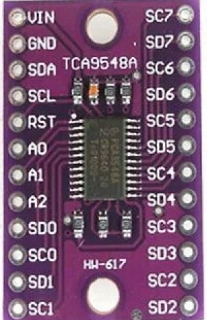
The TCA9548A is an I2C-based multiplexer that allows multiple I2C devices with the same address to coexist on a single bus. It achieves this by providing eight separate downstream I2C channels, each of which can be individually enabled or disabled. This makes it an essential component for applications requiring multiple identical I2C devices or complex I2C bus architectures.
Explore Projects Built with Multiplexer


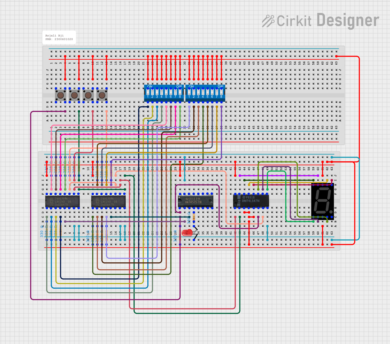

Explore Projects Built with Multiplexer
Common Applications and Use Cases
- Expanding I2C bus capacity in microcontroller projects
- Connecting multiple sensors or devices with identical I2C addresses
- Signal routing in data acquisition systems
- Multi-channel communication in robotics and automation systems
Technical Specifications
The TCA9548A is a versatile and efficient device with the following key specifications:
| Parameter | Value |
|---|---|
| Operating Voltage Range | 1.65V to 5.5V |
| I2C Bus Speed | Up to 400 kHz (Fast Mode) |
| Number of Channels | 8 |
| I2C Address Range | 0x70 to 0x77 (configurable) |
| Maximum Sink Current | 25 mA per channel |
| Operating Temperature Range | -40°C to +85°C |
| Package Type | TSSOP-24 |
Pin Configuration and Descriptions
The TCA9548A comes in a 24-pin TSSOP package. Below is the pin configuration:
| Pin Number | Pin Name | Description |
|---|---|---|
| 1 | A0 | Address selection bit 0 |
| 2 | A1 | Address selection bit 1 |
| 3 | A2 | Address selection bit 2 |
| 4 | RESET | Active-low reset pin |
| 5 | GND | Ground |
| 6 | SCL | I2C clock line |
| 7 | SDA | I2C data line |
| 8-15 | SD0-SD7 | Downstream I2C data lines for channels 0 to 7 |
| 16-23 | SC0-SC7 | Downstream I2C clock lines for channels 0 to 7 |
| 24 | VCC | Power supply input |
Usage Instructions
How to Use the TCA9548A in a Circuit
- Power Supply: Connect the VCC pin to a voltage source within the range of 1.65V to 5.5V and the GND pin to ground.
- I2C Address Configuration: Use the A0, A1, and A2 pins to set the I2C address of the multiplexer. These pins can be connected to VCC or GND to configure the address (0x70 to 0x77).
- I2C Bus Connection: Connect the SCL and SDA pins to the I2C bus of your microcontroller or host device.
- Downstream Channels: Connect the I2C devices to the appropriate downstream channels (SC0-SC7 and SD0-SD7).
- Reset: Optionally, connect the RESET pin to a GPIO pin on your microcontroller for manual or software-controlled resets.
Important Considerations and Best Practices
- Ensure that pull-up resistors are present on the I2C lines (SCL and SDA) of both the upstream and downstream buses.
- Avoid enabling multiple channels simultaneously unless required, as this can cause bus contention.
- Use the RESET pin to recover from bus errors or to reinitialize the device.
Example Code for Arduino UNO
Below is an example of how to use the TCA9548A with an Arduino UNO to communicate with a sensor on channel 0:
#include <Wire.h> // Include the Wire library for I2C communication

#define TCA9548A_ADDRESS 0x70 // Default I2C address of the TCA9548A

// Function to select a specific channel on the TCA9548A
void selectChannel(uint8_t channel) {
  if (channel > 7) return; // Ensure the channel is within the valid range (0-7)
  Wire.beginTransmission(TCA9548A_ADDRESS);
  Wire.write(1 << channel); // Send the channel selection command
  Wire.endTransmission();
}

void setup() {
  Wire.begin(); // Initialize I2C communication
  Serial.begin(9600); // Initialize serial communication for debugging

  // Select channel 0
  selectChannel(0);

  // Example: Communicate with a sensor on channel 0
  Wire.beginTransmission(0x40); // Replace 0x40 with the sensor's I2C address
  Wire.write(0x00); // Example command to the sensor
  Wire.endTransmission();
}

void loop() {
  // Add your main code here
}
Troubleshooting and FAQs
Common Issues and Solutions
I2C Devices Not Responding
- Cause: Incorrect I2C address configuration or channel selection.
- Solution: Verify the address pins (A0, A1, A2) and ensure the correct channel is selected using the appropriate command.
Bus Contention or Communication Errors
- Cause: Multiple channels enabled simultaneously or insufficient pull-up resistors.
- Solution: Enable only one channel at a time and ensure proper pull-up resistors are in place.
Device Not Powering On
- Cause: Incorrect power supply voltage or loose connections.
- Solution: Verify the VCC and GND connections and ensure the supply voltage is within the specified range.
FAQs
Can I use the TCA9548A with 3.3V and 5V devices on the same bus?
- Yes, but you must ensure proper level shifting between the devices if they operate at different voltage levels.
What happens if I enable multiple channels at once?
- Enabling multiple channels can cause bus contention, leading to communication errors. It is recommended to enable only one channel at a time.
How do I reset the TCA9548A?
- You can reset the device by pulling the RESET pin low for a brief period or by cycling the power supply.
By following this documentation, you can effectively integrate the TCA9548A multiplexer into your projects and troubleshoot common issues with ease.