How to Use LILYGO T-CALL A7670 v1: Examples, Pinouts, and Specs
Introduction
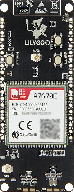
The LILYGO T-CALL A7670 v1 is a compact development board designed for Internet of Things (IoT) applications. It features the A7670 cellular module, which supports GSM/GPRS communication, making it ideal for projects requiring wireless connectivity. This board includes a built-in SIM card slot, battery management capabilities, and multiple GPIO pins for interfacing with sensors, actuators, and other peripherals.
Explore Projects Built with LILYGO T-CALL A7670 v1


Explore Projects Built with LILYGO T-CALL A7670 v1
Common Applications and Use Cases
- Remote monitoring and control systems
- IoT devices requiring cellular connectivity
- GPS tracking and location-based services
- Smart agriculture and environmental monitoring
- Home automation and security systems
Technical Specifications
Below are the key technical details of the LILYGO T-CALL A7670 v1:
| Specification | Details |
|---|---|
| Cellular Module | A7670 (supports GSM/GPRS communication) |
| Frequency Bands | GSM: 850/900/1800/1900 MHz |
| SIM Card Slot | Nano SIM card slot |
| Power Supply | 5V via USB Type-C or 3.7V LiPo battery |
| Battery Management | Integrated charging circuit for LiPo batteries |
| GPIO Pins | Multiple GPIO pins for interfacing with external devices |
| Communication Interfaces | UART, I2C, SPI |
| Antenna | External antenna connector for cellular communication |
| Dimensions | Compact form factor (approx. 50mm x 25mm) |
| Operating Temperature | -40°C to +85°C |
Pin Configuration and Descriptions
The LILYGO T-CALL A7670 v1 features a variety of pins for interfacing with external components. Below is the pinout description:
| Pin | Label | Description |
|---|---|---|
| 1 | 3V3 | 3.3V power output |
| 2 | GND | Ground |
| 3 | TXD | UART Transmit (TX) |
| 4 | RXD | UART Receive (RX) |
| 5 | GPIO0 | General-purpose input/output pin |
| 6 | GPIO1 | General-purpose input/output pin |
| 7 | I2C_SCL | I2C Clock Line |
| 8 | I2C_SDA | I2C Data Line |
| 9 | BAT | Battery input (3.7V LiPo) |
| 10 | USB | USB Type-C input for power and programming |
Usage Instructions
How to Use the Component in a Circuit
Powering the Board:
- Connect a 5V power source via the USB Type-C port or use a 3.7V LiPo battery connected to the BAT pin.
- Ensure the battery is properly connected to avoid reverse polarity damage.
Inserting the SIM Card:
- Insert a Nano SIM card into the built-in SIM card slot. Ensure the SIM card is activated and has a data plan.
Connecting Peripherals:
- Use the GPIO pins to connect sensors, actuators, or other devices. Refer to the pin configuration table for proper connections.
Programming the Board:
- The board can be programmed using the Arduino IDE. Install the necessary libraries for the A7670 module and configure the serial communication settings.
Important Considerations and Best Practices
- Use an external antenna for better cellular signal reception.
- Ensure the SIM card is properly seated in the slot to avoid connectivity issues.
- Avoid exceeding the voltage and current ratings of the GPIO pins.
- Use proper decoupling capacitors when connecting external components to reduce noise.
Example Code for Arduino UNO
Below is an example code snippet to send an SMS using the LILYGO T-CALL A7670 v1:
#include <SoftwareSerial.h>

// Define RX and TX pins for SoftwareSerial
SoftwareSerial mySerial(4, 5); // RX, TX

void setup() {
  // Initialize serial communication
  Serial.begin(9600);
  mySerial.begin(9600);

  // Wait for the module to initialize
  delay(1000);
  Serial.println("Initializing A7670 module...");

  // Send AT command to check communication
  mySerial.println("AT");
  delay(1000);
  while (mySerial.available()) {
    Serial.write(mySerial.read());
  }

  // Set SMS text mode
  mySerial.println("AT+CMGF=1"); // Set SMS to text mode
  delay(1000);

  // Send SMS
  mySerial.println("AT+CMGS=\"+1234567890\""); // Replace with recipient's phone number
  delay(1000);
  mySerial.println("Hello from LILYGO T-CALL A7670!"); // SMS content
  delay(1000);
  mySerial.write(26); // Send Ctrl+Z to indicate end of message
  delay(5000);

  Serial.println("SMS sent!");
}

void loop() {
  // No actions in the loop
}
Note: Replace +1234567890 with the recipient's phone number. Ensure the SIM card has sufficient balance or an active data plan.
Troubleshooting and FAQs
Common Issues and Solutions
No Power to the Board:
- Ensure the USB cable or battery is properly connected.
- Check the power source for sufficient voltage and current.
SIM Card Not Detected:
- Verify that the SIM card is inserted correctly.
- Ensure the SIM card is activated and supports GSM/GPRS.
No Cellular Signal:
- Check the antenna connection and ensure it is securely attached.
- Move to an area with better cellular coverage.
Unable to Send SMS or Connect to Network:
- Verify the APN settings for your SIM card provider.
- Ensure the correct AT commands are used in the code.
FAQs
Q: Can I use this board with a 5V power supply?
A: Yes, the board can be powered via the USB Type-C port with a 5V power supply.
Q: Does the board support 4G or LTE?
A: No, the A7670 module supports GSM/GPRS communication only.
Q: How do I update the firmware of the A7670 module?
A: Firmware updates can be performed using the UART interface. Refer to the manufacturer's documentation for detailed instructions.
Q: Can I use this board with an Arduino UNO?
A: Yes, the board can be interfaced with an Arduino UNO using the UART pins (TXD and RXD). Use a level shifter if necessary to match voltage levels.