How to Use Morse Switch: Examples, Pinouts, and Specs
Introduction
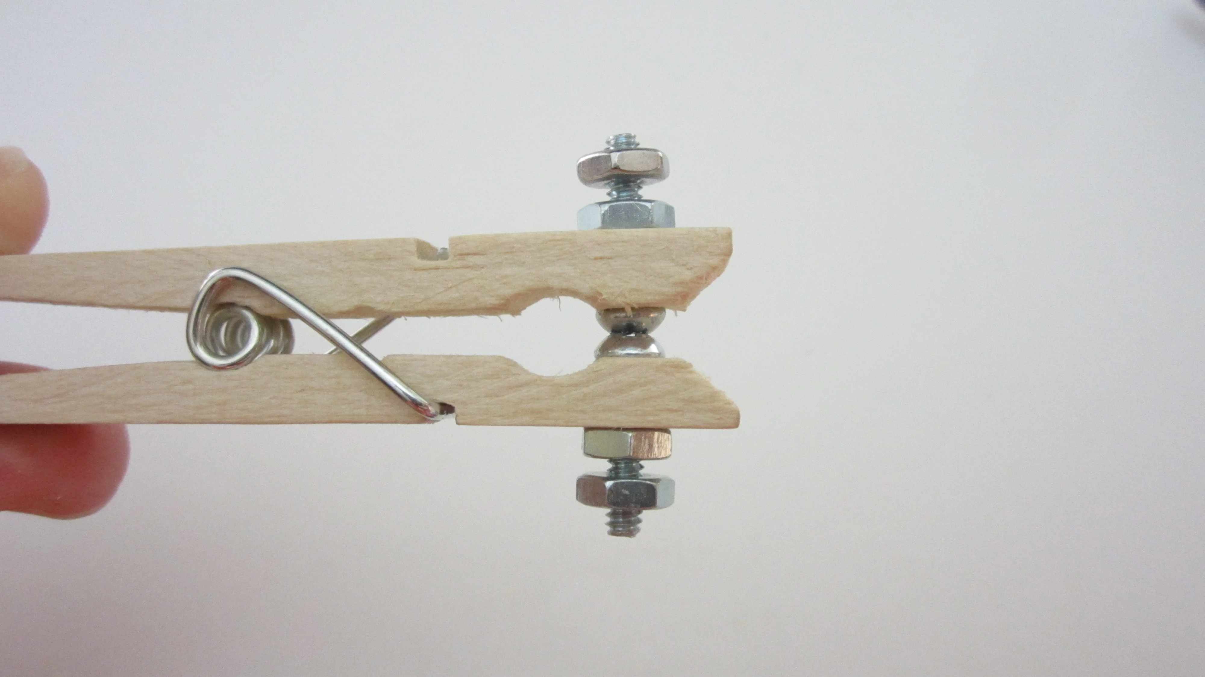
The Morse Switch, manufactured by Pio XII, is a manual electromechanical switch that operates using a lever or toggle mechanism. It is designed to allow or interrupt the flow of current in a circuit, providing a simple means of control or input. This switch is commonly used in applications such as telegraph systems, user input for control panels, and educational projects to demonstrate basic principles of electrical circuits.
Explore Projects Built with Morse Switch

Explore Projects Built with Morse Switch
Common Applications and Use Cases
- Telegraph systems for sending Morse code
- Control panels for machinery or electronic devices
- Educational projects to teach circuit design and control
- Hobbyist projects for DIY electronics
- Interactive installations requiring manual input
Technical Specifications
Key Technical Details
- Voltage Rating: Typically 5V to 24V DC
- Current Rating: Up to 2A (depending on model)
- Contact Type: Single Pole, Single Throw (SPST)
- Contact Resistance: Typically less than 50 milliohms
- Insulation Resistance: Greater than 100M ohms at 500V DC
- Mechanical Life: Up to 1,000,000 cycles
- Operating Temperature: -20°C to 70°C
Pin Configuration and Descriptions
| Pin Number | Description |
|---|---|
| 1 | Common (C) |
| 2 | Normally Open (NO) |
Note: The Morse Switch is a simple two-pin device with one input (Common) and one output (Normally Open). When the lever is actuated, the circuit between these two pins is completed.
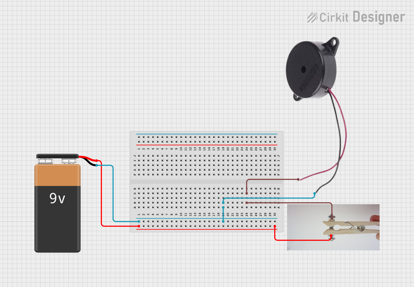
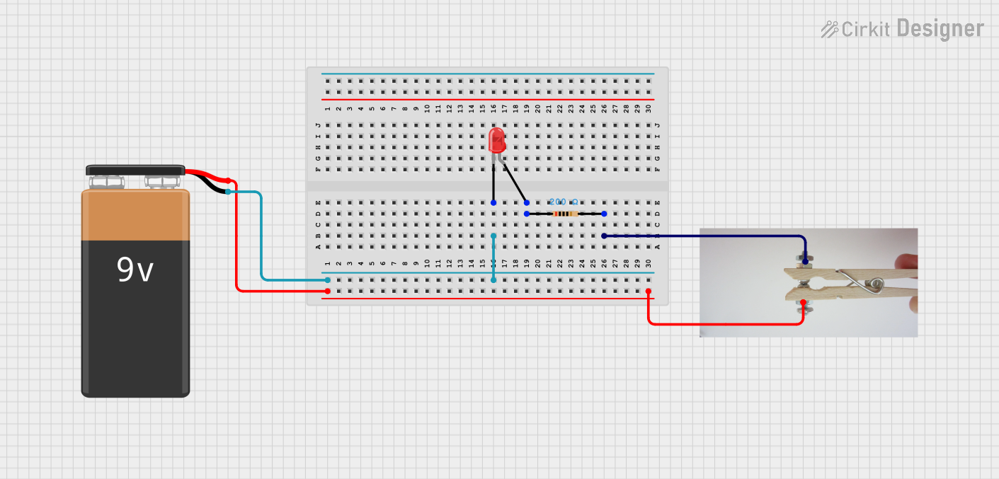
Usage Instructions
How to Use the Component in a Circuit
- Power Off: Ensure that the power supply to the circuit is turned off before installing the switch.
- Wiring: Connect the common pin (Pin 1) to one side of the power source or to the circuit you wish to control. Connect the normally open pin (Pin 2) to the load (e.g., LED, relay, or other devices).
- Mounting: Secure the Morse Switch in the desired location, ensuring that it is accessible for manual operation.
- Testing: Once installed, turn on the power and test the switch by toggling the lever. The connected load should activate when the switch is in the 'on' position.
Important Considerations and Best Practices
- Current Limitation: Do not exceed the current rating of the switch to avoid damage.
- Debouncing: In digital applications, consider implementing a debounce circuit or software debouncing to prevent false triggering due to mechanical bounce.
- Secure Connections: Ensure all connections are secure to prevent intermittent operation.
- Environmental Factors: Avoid using the switch in environments that exceed its operating temperature range or where it may be exposed to moisture or corrosive substances.
Troubleshooting and FAQs
Common Issues
- Intermittent Operation: Check for loose connections or damage to the switch.
- No Operation: Verify that the power supply is functioning and that the switch is properly wired to the circuit.
- Excessive Bouncing: Implement a debounce circuit or adjust the debounce time in software.
Solutions and Tips for Troubleshooting
- Check Connections: Re-solder or tighten connections if they are loose.
- Inspect for Damage: Look for any physical damage to the switch that might prevent proper operation.
- Test with Multimeter: Use a multimeter to check for continuity when the switch is in the 'on' position.
FAQs
Q: Can the Morse Switch be used with AC voltage? A: It is primarily designed for low-voltage DC applications. Check the manufacturer's specifications for AC ratings.
Q: Is the Morse Switch suitable for high-power applications? A: No, it is intended for low-power applications. Using it beyond its rated current can be hazardous.
Q: How can I prevent contact oxidation over time? A: Use the switch regularly to prevent oxidation and ensure a clean contact surface. Avoid environments with high humidity.
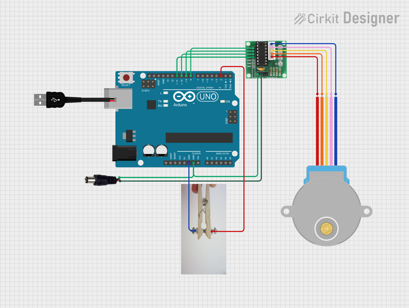
Example Code for Arduino UNO
// Define Morse Switch pin
const int morseSwitchPin = 2; // Connect Morse Switch to digital pin 2

void setup() {
  pinMode(morseSwitchPin, INPUT_PULLUP); // Set the Morse Switch pin as input with internal pull-up
  Serial.begin(9600); // Start serial communication at 9600 baud rate
}

void loop() {
  // Read the state of the Morse Switch
  int switchState = digitalRead(morseSwitchPin);

  // Check if the switch is pressed
  if (switchState == LOW) {
    // Morse Switch is in the 'on' position
    Serial.println("Switch ON");
  } else {
    // Morse Switch is in the 'off' position
    Serial.println("Switch OFF");
  }

  delay(50); // Debounce delay
}
Note: The above code assumes that the Morse Switch is connected to digital pin 2 of the Arduino UNO. The internal pull-up resistor is used to ensure a high signal when the switch is open. When the switch is closed, the pin is pulled to ground (LOW), and the message "Switch ON" is printed to the serial monitor.