Cirkit Designer Logo
Cirkit Designer
Your all-in-one circuit design IDE
Home / 
Component Documentation

How to Use CH9121 Ethernet Module: Examples, Pinouts, and Specs

Image of CH9121 Ethernet Module
Cirkit Designer LogoDesign with CH9121 Ethernet Module in Cirkit Designer

Introduction

The CH9121 is a compact and versatile Ethernet module designed to enable devices to connect to a network via Ethernet. It supports TCP/IP protocols, making it an ideal choice for applications requiring reliable wired communication. The module is widely used in IoT devices, industrial automation, embedded systems, and other applications where stable and secure Ethernet connectivity is essential. Its small form factor and ease of integration make it a popular choice for developers and engineers.

Explore Projects Built with CH9121 Ethernet Module

Use Cirkit Designer to design, explore, and prototype these projects online. Some projects support real-time simulation. Click "Open Project" to start designing instantly!
ESP32 and W5500 Ethernet Module Controlled 8-Channel Relay
Image of ESP32 38Pin 8 Channel Relay USB-C: A project utilizing CH9121 Ethernet Module in a practical application
This circuit enables Ethernet connectivity and device control through an ESP32 microcontroller. It uses the W5500 Ethernet module for network communication and controls an 8-channel relay module for switching external devices or loads.
Cirkit Designer LogoOpen Project in Cirkit Designer
STM32F4 and ENC28J60 Ethernet-Enabled Microcontroller Project
Image of youssef: A project utilizing CH9121 Ethernet Module in a practical application
This circuit integrates an STM32F4 BlackPill microcontroller with an ENC28J60 Ethernet Board to enable Ethernet connectivity. The microcontroller communicates with the Ethernet board via SPI, with connections for power, ground, and SPI signals (SI, SO, SCK, and CS). The provided code is a basic template for further development.
Cirkit Designer LogoOpen Project in Cirkit Designer
ESP32-Based Environmental Monitoring System with Ethernet Connectivity
Image of ESP32 38Pin USBMicro: A project utilizing CH9121 Ethernet Module in a practical application
This circuit features an ESP32 microcontroller interfaced with a W5500 Ethernet module for network connectivity, a DHT22 sensor for measuring temperature and humidity, and an Adafruit SHTC3 sensor for additional temperature and humidity readings. The ZMPT101B module is connected to the ESP32 for voltage measurement in an AC power line. The ESP32 manages data collection from the sensors and communicates with the Ethernet module, likely for data logging or remote monitoring purposes.
Cirkit Designer LogoOpen Project in Cirkit Designer
ESP32-Based Environmental Monitoring and Home Automation System with Ethernet Connectivity
Image of ESP32 30Pin 3Phase AC Box W5500 Ethernet Standard: A project utilizing CH9121 Ethernet Module in a practical application
This circuit features an ESP32 microcontroller interfaced with a W5500 Ethernet module for network connectivity, a DHT22 sensor for measuring temperature and humidity, a ZMPT101B module for AC voltage sensing, and an Adafruit SHTC3 sensor for additional temperature and humidity readings. The ESP32 also controls a 4-channel relay module for switching external devices. The sensors and Ethernet module communicate with the ESP32 via GPIO pins, with the W5500 using SPI and the SHTC3 using I2C. Common ground and power lines are shared among the components.
Cirkit Designer LogoOpen Project in Cirkit Designer

Explore Projects Built with CH9121 Ethernet Module

Use Cirkit Designer to design, explore, and prototype these projects online. Some projects support real-time simulation. Click "Open Project" to start designing instantly!
Image of ESP32 38Pin 8 Channel Relay USB-C: A project utilizing CH9121 Ethernet Module in a practical application
ESP32 and W5500 Ethernet Module Controlled 8-Channel Relay
This circuit enables Ethernet connectivity and device control through an ESP32 microcontroller. It uses the W5500 Ethernet module for network communication and controls an 8-channel relay module for switching external devices or loads.
Cirkit Designer LogoOpen Project in Cirkit Designer
Image of youssef: A project utilizing CH9121 Ethernet Module in a practical application
STM32F4 and ENC28J60 Ethernet-Enabled Microcontroller Project
This circuit integrates an STM32F4 BlackPill microcontroller with an ENC28J60 Ethernet Board to enable Ethernet connectivity. The microcontroller communicates with the Ethernet board via SPI, with connections for power, ground, and SPI signals (SI, SO, SCK, and CS). The provided code is a basic template for further development.
Cirkit Designer LogoOpen Project in Cirkit Designer
Image of ESP32 38Pin USBMicro: A project utilizing CH9121 Ethernet Module in a practical application
ESP32-Based Environmental Monitoring System with Ethernet Connectivity
This circuit features an ESP32 microcontroller interfaced with a W5500 Ethernet module for network connectivity, a DHT22 sensor for measuring temperature and humidity, and an Adafruit SHTC3 sensor for additional temperature and humidity readings. The ZMPT101B module is connected to the ESP32 for voltage measurement in an AC power line. The ESP32 manages data collection from the sensors and communicates with the Ethernet module, likely for data logging or remote monitoring purposes.
Cirkit Designer LogoOpen Project in Cirkit Designer
Image of ESP32 30Pin 3Phase AC Box W5500 Ethernet Standard: A project utilizing CH9121 Ethernet Module in a practical application
ESP32-Based Environmental Monitoring and Home Automation System with Ethernet Connectivity
This circuit features an ESP32 microcontroller interfaced with a W5500 Ethernet module for network connectivity, a DHT22 sensor for measuring temperature and humidity, a ZMPT101B module for AC voltage sensing, and an Adafruit SHTC3 sensor for additional temperature and humidity readings. The ESP32 also controls a 4-channel relay module for switching external devices. The sensors and Ethernet module communicate with the ESP32 via GPIO pins, with the W5500 using SPI and the SHTC3 using I2C. Common ground and power lines are shared among the components.
Cirkit Designer LogoOpen Project in Cirkit Designer

Common Applications

  • IoT devices requiring wired network connectivity
  • Industrial automation systems
  • Embedded systems with Ethernet communication
  • Remote monitoring and control systems
  • Data acquisition and logging devices

Technical Specifications

Key Technical Details

Parameter Value
Supply Voltage 3.3V
Operating Current ~120mA
Communication Protocols TCP, UDP
Baud Rate (UART) Configurable (default: 9600 bps)
Ethernet Speed 10/100 Mbps
Operating Temperature -40°C to +85°C
Dimensions 28mm x 20mm

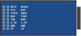
Pin Configuration and Descriptions

Pin Number Pin Name Description
1 VCC Power supply input (3.3V)
2 GND Ground
3 TXD UART Transmit Data
4 RXD UART Receive Data
5 RST Reset pin (active low)
6 CFG Configuration mode selection (connect to GND for configuration mode)
7 ETH_TX+ Ethernet transmit positive
8 ETH_TX- Ethernet transmit negative
9 ETH_RX+ Ethernet receive positive
10 ETH_RX- Ethernet receive negative

Usage Instructions

How to Use the CH9121 in a Circuit

  1. Power Supply: Connect the VCC pin to a 3.3V power source and the GND pin to ground.
  2. UART Communication: Connect the TXD and RXD pins to the UART pins of your microcontroller or development board (e.g., Arduino UNO).
  3. Ethernet Connection: Connect the Ethernet pins (ETH_TX+, ETH_TX-, ETH_RX+, ETH_RX-) to an RJ45 Ethernet jack.
  4. Configuration Mode: To configure the module, pull the CFG pin low (connect it to GND) and use a serial terminal to set parameters such as IP address, baud rate, and communication mode.
  5. Normal Operation: For normal operation, leave the CFG pin unconnected or pull it high.

Important Considerations and Best Practices

  • Ensure the module is powered with a stable 3.3V supply to avoid damage or instability.
  • Use proper Ethernet cables and connectors to ensure reliable communication.
  • Configure the module's IP address and other network settings to match your network environment.
  • Avoid long UART cables to minimize signal degradation.
  • If using with an Arduino UNO, use a level shifter or voltage divider to safely interface the 5V UART pins with the 3.3V CH9121 pins.

Example: Connecting CH9121 to Arduino UNO

Below is an example of how to use the CH9121 with an Arduino UNO to send data over Ethernet.

Wiring

  • CH9121 TXDArduino RX (Pin 0) (use a level shifter or voltage divider)
  • CH9121 RXDArduino TX (Pin 1) (use a level shifter or voltage divider)
  • CH9121 VCC3.3V
  • CH9121 GNDGND
  • CH9121 Ethernet PinsRJ45 Ethernet Jack

Code Example

#include <SoftwareSerial.h>

// Define RX and TX pins for SoftwareSerial
SoftwareSerial CH9121(2, 3); // RX = Pin 2, TX = Pin 3

void setup() {
  Serial.begin(9600); // Initialize Serial Monitor
  CH9121.begin(9600); // Initialize CH9121 UART communication

  // Send a test message to the CH9121
  Serial.println("Initializing CH9121...");
  CH9121.println("Hello, Ethernet!");
}

void loop() {
  // Check if data is available from CH9121
  if (CH9121.available()) {
    String data = CH9121.readString(); // Read data from CH9121
    Serial.print("Received from CH9121: ");
    Serial.println(data); // Print received data to Serial Monitor
  }

  // Check if data is available from Serial Monitor
  if (Serial.available()) {
    String data = Serial.readString(); // Read data from Serial Monitor
    CH9121.println(data); // Send data to CH9121
  }
}

Notes

  • Use the CFG pin to configure the module before running the code.
  • Ensure the baud rate in the code matches the CH9121's configured baud rate.

Troubleshooting and FAQs

Common Issues and Solutions

  1. No Ethernet Connectivity

    • Ensure the Ethernet cable is properly connected and functional.
    • Verify the module's IP address and network settings are correctly configured.
  2. UART Communication Issues

    • Check the baud rate settings on both the CH9121 and the microcontroller.
    • Use a level shifter or voltage divider if interfacing with a 5V microcontroller.
  3. Module Not Responding

    • Verify the power supply voltage is 3.3V and stable.
    • Check the RST pin to ensure the module is not held in reset state.
  4. Data Loss or Corruption

    • Use shorter UART cables to reduce noise and signal degradation.
    • Ensure proper grounding between the CH9121 and the microcontroller.

FAQs

Q: Can the CH9121 be used with a 5V microcontroller?
A: Yes, but you must use a level shifter or voltage divider to safely interface the 3.3V UART pins with the 5V logic levels.

Q: How do I configure the CH9121?
A: Pull the CFG pin low and use a serial terminal to configure parameters such as IP address, baud rate, and communication mode.

Q: What is the default baud rate of the CH9121?
A: The default baud rate is 9600 bps.

Q: Can the CH9121 work with both TCP and UDP protocols?
A: Yes, the CH9121 supports both TCP and UDP communication protocols.