Cirkit Designer
Your all-in-one circuit design IDE
Home /
Component Documentation
How to Use nrf24l01 wireless 3.3 v adaptor: Examples, Pinouts, and Specs
Introduction
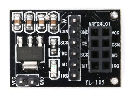
The nRF24L01 Wireless 3.3V Adapter is a module designed to facilitate the use of the nRF24L01 wireless transceiver with 3.3V systems. This adapter ensures stable voltage regulation and simplifies connectivity, making it an essential component for wireless communication projects. It is commonly used in applications such as remote control systems, wireless sensors, and IoT devices.
Explore Projects Built with nrf24l01 wireless 3.3 v adaptor
Arduino Nano Wireless Communication System with nRF24L01 Module

This circuit connects an nRF24L01 wireless transceiver module to an Arduino Nano microcontroller through an adapter board. The Arduino Nano is configured to communicate with the nRF24L01 via SPI (Serial Peripheral Interface), using pins D9 and D10 for chip enable (CE) and chip select (CSN), and pins D11 to D13 for the SPI bus (MOSI, MISO, SCK). An electrolytic capacitor is connected across the power supply lines likely for power stabilization.
Arduino Nano and NRF24L01 Wireless Communication Module
This circuit features an Arduino Nano microcontroller interfaced with an NRF24L01 wireless transceiver module via an adapter. The setup is designed for wireless communication, with the Arduino controlling the transceiver through SPI and digital I/O pins, and the code provided is a basic template for further development.
Arduino Nano and NRF24L01 Wireless Communication Module
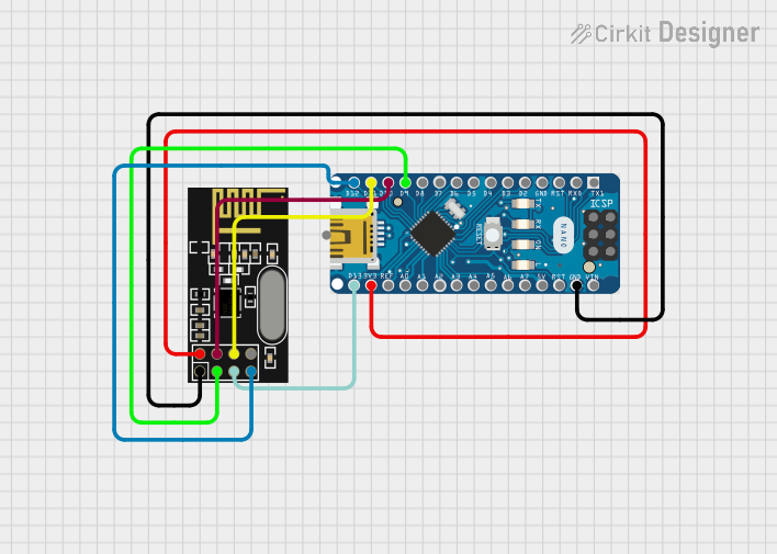
This circuit is designed to enable wireless communication capabilities for the Arduino Nano using the NRF24L01 module. It is wired for SPI communication with additional control lines for chip enable and selection. The Arduino is powered by its 3.3V output, and the provided code template is prepared for the user to implement the desired communication protocol.
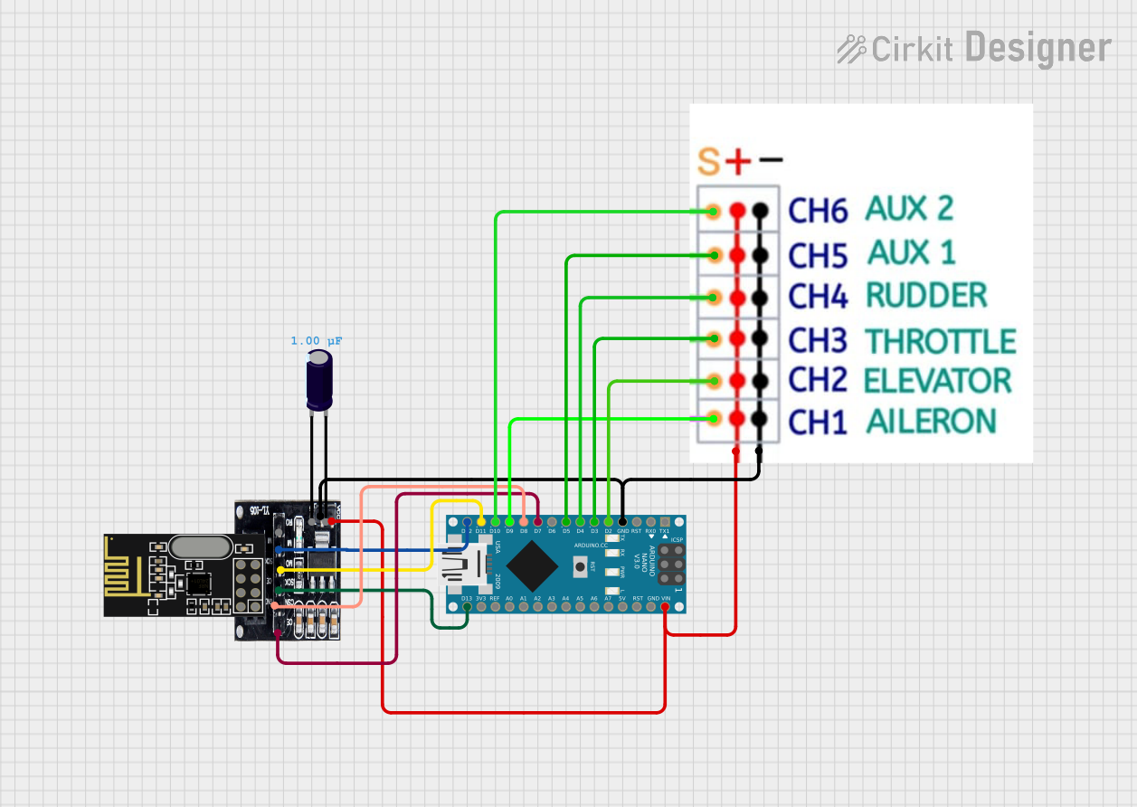
Arduino UNO with NRF24L01 Wireless Communication and Analog Input Control
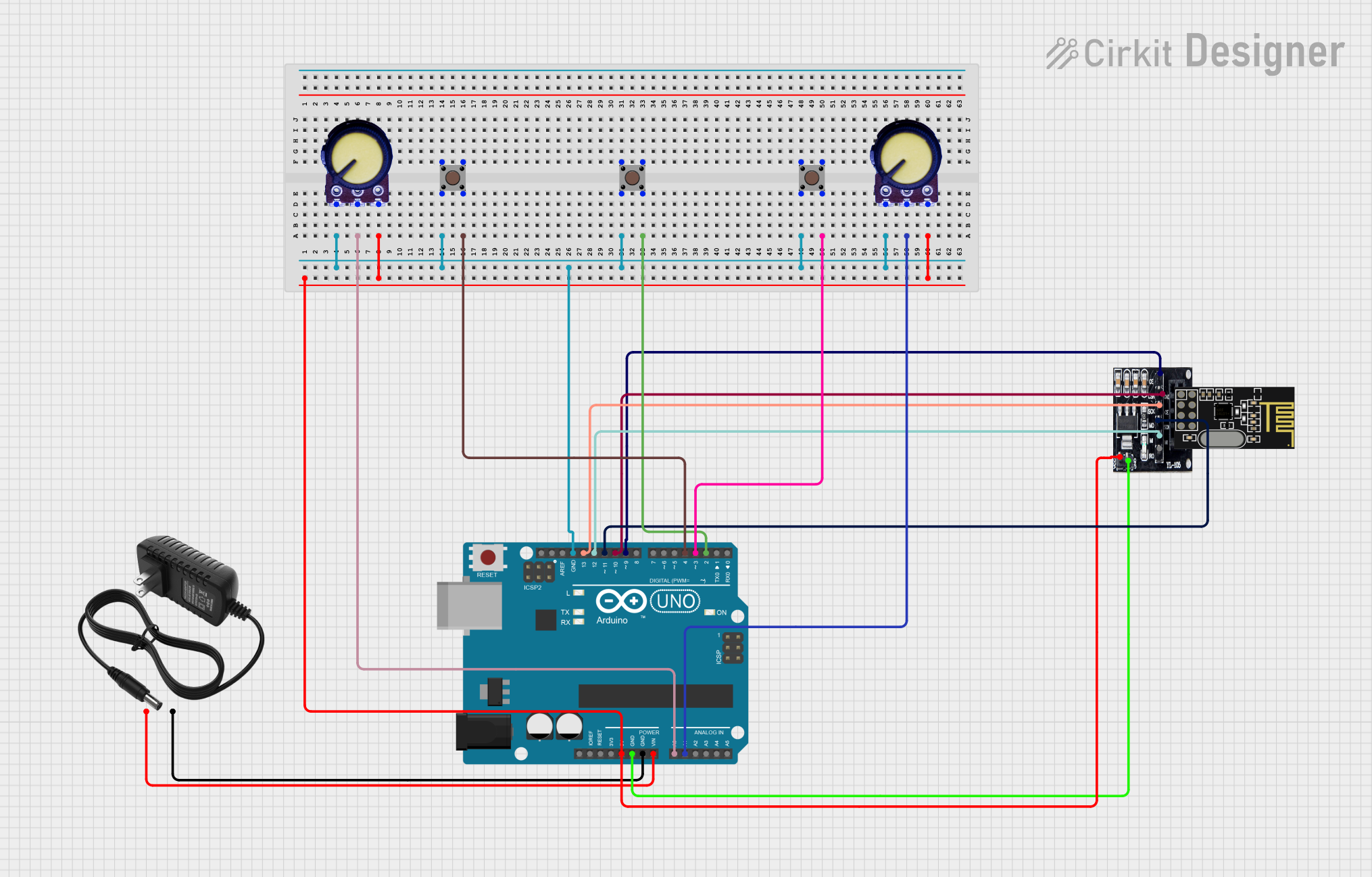
This circuit features an Arduino UNO connected to an NRF24L01 Adapter for wireless communication, powered by a 12V supply. It includes two potentiometers for analog input and three pushbuttons for digital input, with the Arduino managing these interfaces and potentially processing and transmitting data wirelessly.
Explore Projects Built with nrf24l01 wireless 3.3 v adaptor
Arduino Nano Wireless Communication System with nRF24L01 Module
This circuit connects an nRF24L01 wireless transceiver module to an Arduino Nano microcontroller through an adapter board. The Arduino Nano is configured to communicate with the nRF24L01 via SPI (Serial Peripheral Interface), using pins D9 and D10 for chip enable (CE) and chip select (CSN), and pins D11 to D13 for the SPI bus (MOSI, MISO, SCK). An electrolytic capacitor is connected across the power supply lines likely for power stabilization.
Arduino Nano and NRF24L01 Wireless Communication Module
This circuit features an Arduino Nano microcontroller interfaced with an NRF24L01 wireless transceiver module via an adapter. The setup is designed for wireless communication, with the Arduino controlling the transceiver through SPI and digital I/O pins, and the code provided is a basic template for further development.
Arduino Nano and NRF24L01 Wireless Communication Module
This circuit is designed to enable wireless communication capabilities for the Arduino Nano using the NRF24L01 module. It is wired for SPI communication with additional control lines for chip enable and selection. The Arduino is powered by its 3.3V output, and the provided code template is prepared for the user to implement the desired communication protocol.
Arduino UNO with NRF24L01 Wireless Communication and Analog Input Control
This circuit features an Arduino UNO connected to an NRF24L01 Adapter for wireless communication, powered by a 12V supply. It includes two potentiometers for analog input and three pushbuttons for digital input, with the Arduino managing these interfaces and potentially processing and transmitting data wirelessly.
Technical Specifications
Key Technical Details
| Parameter | Value |
|---|---|
| Operating Voltage | 3.3V |
| Input Voltage | 5V (from microcontroller) |
| Current Consumption | 12mA (typical) |
| Communication | SPI |
| Dimensions | 25mm x 18mm |
Pin Configuration and Descriptions
| Pin | Name | Description |
|---|---|---|
| 1 | VCC | Power supply (3.3V) |
| 2 | GND | Ground |
| 3 | CE | Chip Enable (active high) |
| 4 | CSN | Chip Select Not (active low) |
| 5 | SCK | Serial Clock (SPI) |
| 6 | MOSI | Master Out Slave In (SPI) |
| 7 | MISO | Master In Slave Out (SPI) |
| 8 | IRQ | Interrupt Request (optional, not always used) |
Usage Instructions
How to Use the Component in a Circuit
- Power Supply: Connect the VCC pin to a 3.3V power source and the GND pin to the ground.
- SPI Communication: Connect the SPI pins (CE, CSN, SCK, MOSI, MISO) to the corresponding SPI pins on your microcontroller.
- Optional IRQ: If you need interrupt functionality, connect the IRQ pin to an interrupt-capable pin on your microcontroller.
Important Considerations and Best Practices
- Voltage Regulation: Ensure that the VCC pin is supplied with a stable 3.3V. Using a higher voltage can damage the nRF24L01 module.
- Decoupling Capacitors: Place a 10µF and a 0.1µF capacitor close to the VCC and GND pins to filter out noise and provide stable power.
- Antenna Placement: For optimal wireless performance, ensure that the antenna is placed away from large metal objects and other sources of interference.
Example Circuit with Arduino UNO
#include <SPI.h>
#include <nRF24L01.h>
#include <RF24.h>

// CE and CSN pins connected to Arduino pins 9 and 10 respectively
RF24 radio(9, 10);

void setup() {
  Serial.begin(9600);
  radio.begin();
  radio.openWritingPipe(0xF0F0F0F0E1LL); // Set the address
  radio.setPALevel(RF24_PA_MIN);        // Set power level to minimum
  radio.stopListening();                // Set the module as transmitter
}

void loop() {
  const char text[] = "Hello World";
  radio.write(&text, sizeof(text));     // Send the message
  delay(1000);                          // Wait for a second
}
Troubleshooting and FAQs
Common Issues Users Might Face
No Communication Between Modules:
- Solution: Ensure that both modules are set to the same address and channel. Check the wiring and ensure that the SPI connections are correct.
Unstable Connection:
- Solution: Add decoupling capacitors close to the VCC and GND pins. Ensure that the power supply is stable and free from noise.
Module Not Powering On:
- Solution: Verify that the VCC pin is receiving a stable 3.3V. Check for any loose connections or solder joints.
Solutions and Tips for Troubleshooting
- Check Connections: Double-check all connections to ensure they are secure and correctly placed.
- Use a Multimeter: Measure the voltage at the VCC pin to ensure it is 3.3V.
- Library Compatibility: Ensure that you are using a compatible library for the nRF24L01 module, such as the RF24 library for Arduino.
By following this documentation, users can effectively integrate the nRF24L01 Wireless 3.3V Adapter into their projects, ensuring reliable and efficient wireless communication.